

This is the second part of the BGP series. If you just landed on this post, feel free to check out the introductory post linked below. If you are already familiar with BGP basics, you can skip ahead. In this part, we will look at how to configure BGP on Cisco routers, so let’s get started.
As always, if you find this post helpful, press the ‘clap’ button. It means a lot to me and helps me know you enjoy this type of content. If I get enough claps for this series, I’ll make sure to write more on this specific topic.
eBGP Configuration Example
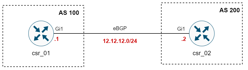
Let's look at an example of how to configure eBGP between two routers. The two routers csr_01 and csr_02 are directly connected and in AS100 and AS200, respectively. You only need a couple of lines of configuration to bring the neighbourship up, though there are caveats which we will cover in detail.
#csr_01

router bgp 100
 neighbor 12.12.12.2 remote-as 200
#csr_02
router bgp 200
neighbor 12.12.12.1 remote-as 100#output from csr_01
csr_01#show ip bgp summary
BGP router identifier 12.12.12.1, local AS number 100
BGP table version is 1, main routing table version 1
Neighbor V AS MsgRcvd MsgSent TblVer InQ OutQ Up/Down State/PfxRcd
12.12.12.2 4 200 113 111 1 0 0 01:39:20 0As you can see above, I've only used two lines of configuration on each router, and the neighbourship comes up. The show ip bgp summary command shows a brief summary of all the BGP peers, but we only have one at the moment.
You can run show ip bgp neighbors x.x.x.x to get detailed information about the session. What you want to see for the BGP state is Established which means the BGP season comes up.
csr_01#show ip bgp neighbors 12.12.12.2
BGP neighbor is 12.12.12.2,  remote AS 200, external link
  BGP version 4, remote router ID 2.2.2.2
  BGP state = Established, up for 00:01:13
  Last read 00:00:20, last write 00:00:20, hold time is 180, keepalive interval is 60 seconds
  Last update received: 00:00:20
  Neighbor sessions:
    1 active, is not multisession capable (disabled)
If there is an issue with forming neighbourship, then you will see a different state under BGP state
address-family ipv4
Sometimes you will see that BGP configuration is placed under an address-family section. Address families in BGP simply define what type of routes we want to exchange.
csr_01#show run | sec router
router bgp 100
 bgp log-neighbor-changes
 neighbor 12.12.12.2 remote-as 200
 !
 address-family ipv4
  neighbor 12.12.12.2 activate
 exit-address-family
csr_02#show run | sec bgp
router bgp 200
bgp log-neighbor-changes
neighbor 12.12.12.1 remote-as 100
!
address-family ipv4
neighbor 12.12.12.1 activate
exit-address-familyIn modern configurations, you usually see the neighbours defined under the global section but activated inside the specific address family. This makes it clear what type of routes the neighbour will exchange and allows you to use the same BGP session for multiple address families if needed.
iBGP Configuration Example
Configuring iBGP is similar to configuring eBGP, with a key difference regarding the Autonomous System numbers. For iBGP, the router's own AS number will be the same as the remote AS number. This similarity in AS numbers is how routers recognize the neighbour as an iBGP connection rather than an eBGP one.
#iBGP example

router bgp 150
 neighbor 15.15.15.2 remote-as 150
BGP Neighbour Key Points
Setting up a BGP neighbour might seem straightforward, but there are a few things to remember that underline the complexity and uniqueness of BGP.
- Neighbour States - BGP neighbours pass through several stages (Idle, Connect, Active, OpenSent, OpenConfirm, and Established) before the connection is fully established.
- TCP Port 179 - BGP uses TCP port 179 for communication between peers, which is different from IGP protocols like OSPF or EIGRP.
- Non-direct Connections - BGP neighbours do not need to be directly connected. As long as there is IP connectivity and the neighbour's IP is reachable, a BGP session can form (more on this later)
- TTL Values - By default, the TTL (Time To Live) value for eBGP sessions is set to 1, requiring direct connectivity, while for iBGP, the default TTL is 255.
- BGP update-source - The
update-sourcecommand in BGP configuration is used to specify the local interface for sending BGP messages to a peer. - Route Advertisement - Configuring BGP neighbours alone does not initiate route advertisement. Specific configurations are needed to begin exchanging routing information.
We will dive into each of these points in more detail to fully understand the intricacies of establishing and maintaining BGP neighborships.
BGP Neighbour States
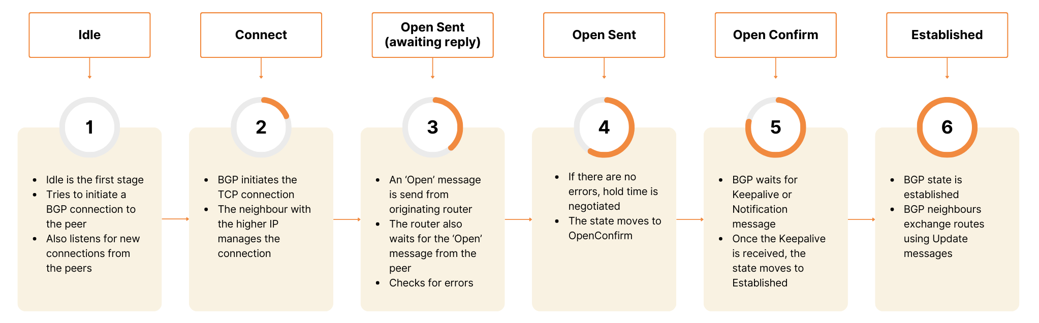
- Idle - This is the initial state of a BGP connection. In this state, BGP is waiting to start the connection process, but it's also listening for incoming connections from peers. If it's configured to initiate connections, it'll try to establish a TCP connection and transition to the state.
- Connect - BGP is actively trying to establish a TCP connection with its neighbour. If it's successful, BGP will send an OPEN message to move to the OpenSent state. If the connection attempt fails, it may either retry the connection, leading to the Active state or revert to Idle.
- Active - In the Active state, BGP is still attempting to establish a TCP connection. If continuous attempts fail, BGP will flip between Active and Connect states.
- OpenSent - A TCP connection is established, and a neighbour message has been sent to the neighbour. This message includes parameters like the BGP version, AS number, hold time, and BGP Identifier (router-ID). It transitions to OpenConfirm upon receiving a proper OPEN message in response.
- OpenConfirm - At this point, BGP awaits a KEEPALIVE or NOTIFICATION message. Upon receiving the neighbour's KEEPALIVE message, the state moves to Established.
- Established - The goal state where BGP peers send and receive UPDATE messages containing route information. The peers are fully connected, and the routers can now exchange routing information freely. The Established state indicates a successful BGP session.
BGP Message Types
BGP uses four types of messages to establish and maintain connections between peers.
- Open Message - Initiates a conversation between BGP peers and establishes a connection. It includes important information like the BGP version, the AS number, and the hold time as we discussed before.
- Update Message - Share route information. This message announces new routes or withdraws previously announced routes. It's the primary way BGP advertises reachable networks.
- Keepalive Message - Let a BGP peer know that the other is still available. These short messages are sent periodically to maintain the connection if no other data is being exchanged.
- Notification Message - Communicates errors or closes a connection. If there’s a problem, a notification message is sent and the BGP session is terminated.
TCP 179 and OPEN Parameters
Here, you can see the different messages via the packet capture. As we discussed before, BGP uses TCP/179 so, the TCP 3-way handshake must complete. The OPEN message contains parameters that should match on both sides.

The BGP OPEN message is the first message sent by each side after the TCP connection has been established, and it's crucial for initiating a BGP session. This message includes several key parameters.
- Version - The BGP version is being used. This must match between peers for the session to be established.
- AS Number - The Autonomous System (AS) number of the sender. The AS number in the OPEN message must match what is configured for the neighbour.
- The Source IP address of the OPEN message must match the IP address configured for the neighbour.
- BGP Identifier - A unique identifier for the BGP router, usually chosen as the highest IP address on the router unless specifically defined (loopback if not a physical interface). The router ID must be unique.
- Hold Timer - The Lowest hold timer is used, and the timers don't need to match.
- Authentication - If you have configured a password for the peering, it must match.
bgp router-id x.x.x.x command under the BGP process.The default BGP hold timer is 180 seconds, and it can be set to 0 to disable it. Keepalive messages are sent every 30 seconds by default, which is one-third of the hold time. A BGP router must receive either a keepalive or an update message before the hold timer expires. If the hold timer does expire, the BGP session is torn down, all routes learned from that neighbour are removed, and an update message is sent to inform peers to withdraw those routes.
Non-direct Connections and TTL (BGP Multihop)
You might be wondering, given that BGP establishes its neighbour relationships over TCP, if it's possible for BGP peers to form a neighborship even when there's an intermediate router between them. It's a valid question, especially considering that TCP/IP is designed to handle multi-hop connectivity. Let's give this a go, shall we?
When you have a router (or multiple routers) sitting between your eBGP peers, and you try to form a neighborship, there's a key element that comes into play, the TTL, or Time to Live, value in the IP packet.
For eBGP, the default TTL value is set to 1, (255 for iBGP peers) which means the packet can't hop to another router. But, if we change the default eBGP TTL value to a higher number, it can indeed pass through multiple routers. This is how eBGP multihop comes into the picture, enabling non-direct connections between eBGP peers.
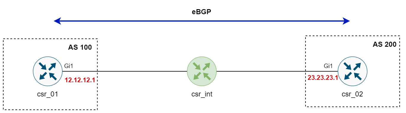
Here, in this example, I have an intermediate router between the eBGP peers and the peers can ping each other so, we know for sure they have IP reachability. However, the eBGP session won't come up (indicated by State - Idle). Even better, the routers won't even attempt to create a connection because they know they are in a different subnet.
csr_01#ping 23.23.23.1
Type escape sequence to abort.
Sending 5, 100-byte ICMP Echos to 23.23.23.1, timeout is 2 seconds:
!!!!!
Success rate is 100 percent (5/5), round-trip min/avg/max = 1/4/17 ms
csr_01#show ip bgp summary
BGP router identifier 12.12.12.1, local AS number 100
BGP table version is 1, main routing table version 1
Neighbor V AS MsgRcvd MsgSent TblVer InQ OutQ Up/Down State/PfxRcd
23.23.23.1 4 200 0 0 1 0 0 never IdleBGP neighbor is 23.23.23.1, remote AS 200, external link
External BGP neighbor not directly connected.
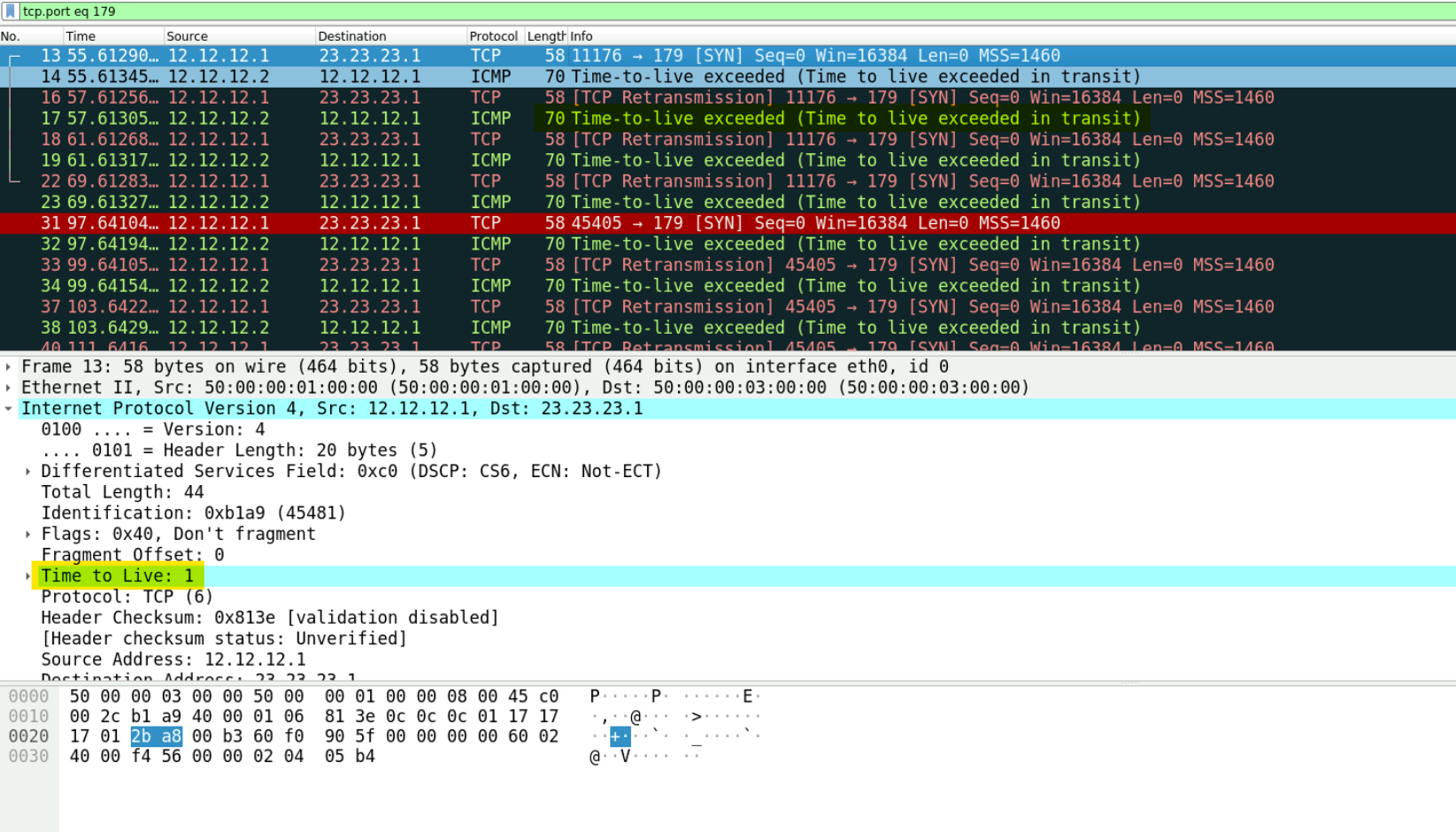
External BGP neighbor configured for connected checks (single-hop no-disable-connected-check)disable-connected-check disables the test that a BGP process runs to check whether the eBGP neighbour IP address belongs to a local directly connected subnet. We could try to disable the connected-check but it will still not work. But, let's try it anyway 😄 As soon as I disable the connected-checks, the routers will try to send the TCP-SYN packet to the peers, as you can see in the video below.
router bgp 100
neighbor 23.23.23.1 disable-connected-checkHowever, since the TTL is set to 1 by default for eBGP peers (255 for iBGP peers). So, the intermediate router will just drop the packet and send a 'Time to live exceeded' message back to the router.
To overcome this, we need to configure BGP multi-hop. Configuring multihop eBGP enables the peers to pass through the other routers to form peer relationships and exchange update messages. The command to enable multihop is ebgp-multihop under the BGP configuration.
#csr_01

router bgp 100
 bgp log-neighbor-changes
 neighbor 23.23.23.1 remote-as 200
 neighbor 23.23.23.1 ebgp-multihop 255
#csr_02
router bgp 200
bgp log-neighbor-changes
neighbor 12.12.12.1 remote-as 100
neighbor 12.12.12.1 ebgp-multihop 255Please note that ebgp-multihop command also disables the connected-check so, you don't have to manually disable it. By default, the multi-hop command uses a TTL value of 255 which can be changed if you need. (neighbor 12.12.12.1 ebgp-multihop TTL_VALUE)
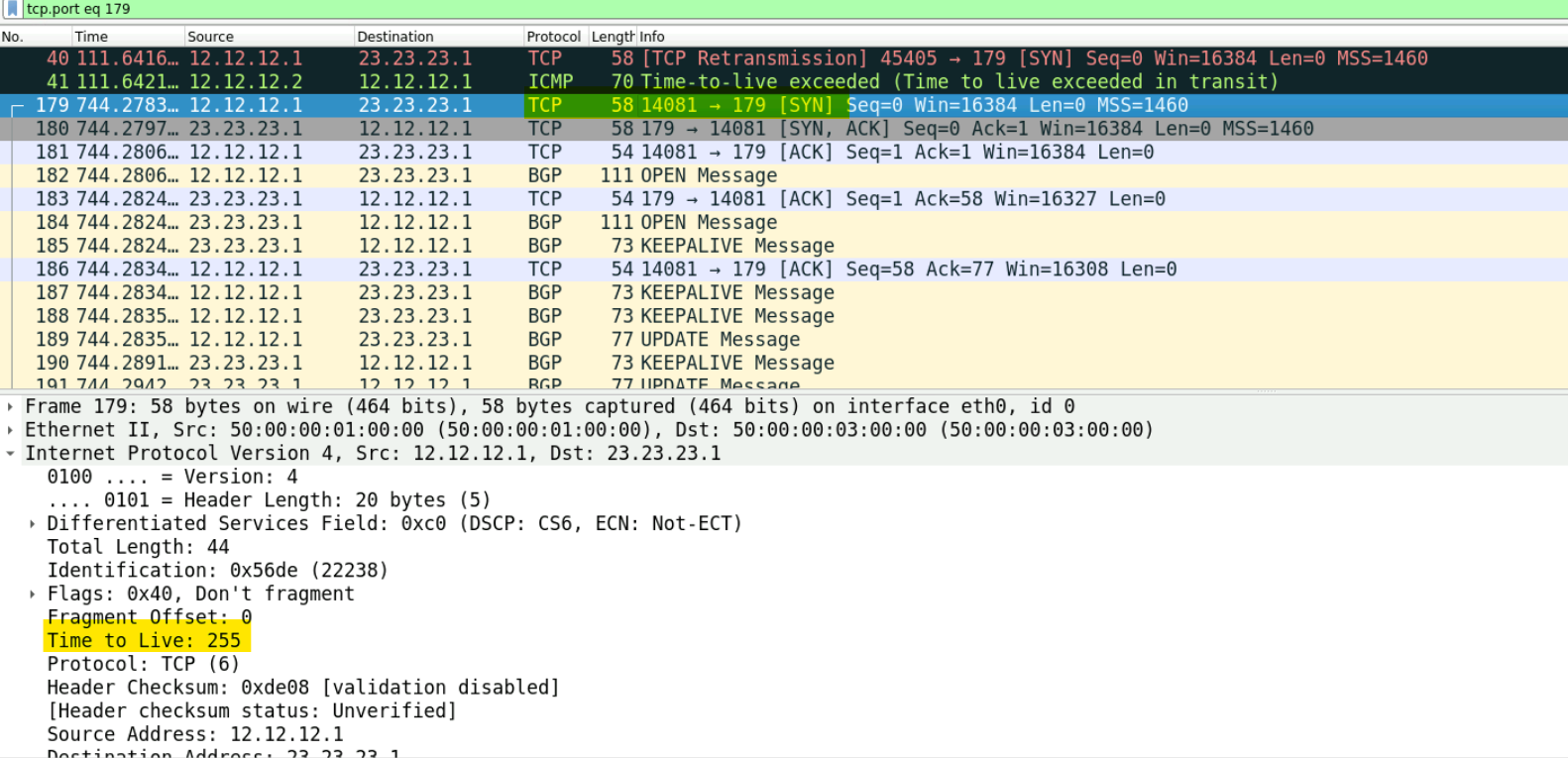
Now, the eBGP session is established and all is working as expected.
csr_02#show ip bgp summary
BGP router identifier 23.23.23.1, local AS number 200
BGP table version is 1, main routing table version 1

Neighbor        V           AS MsgRcvd MsgSent   TblVer  InQ OutQ Up/Down  State/PfxRcd
12.12.12.1      4          100       7       7        1    0    0 00:03:21        0
Having an intermediate router between eBGP peers is uncommon but in the next section, we will look at a more common use case of eBGP multihop.
BGP Update-Source
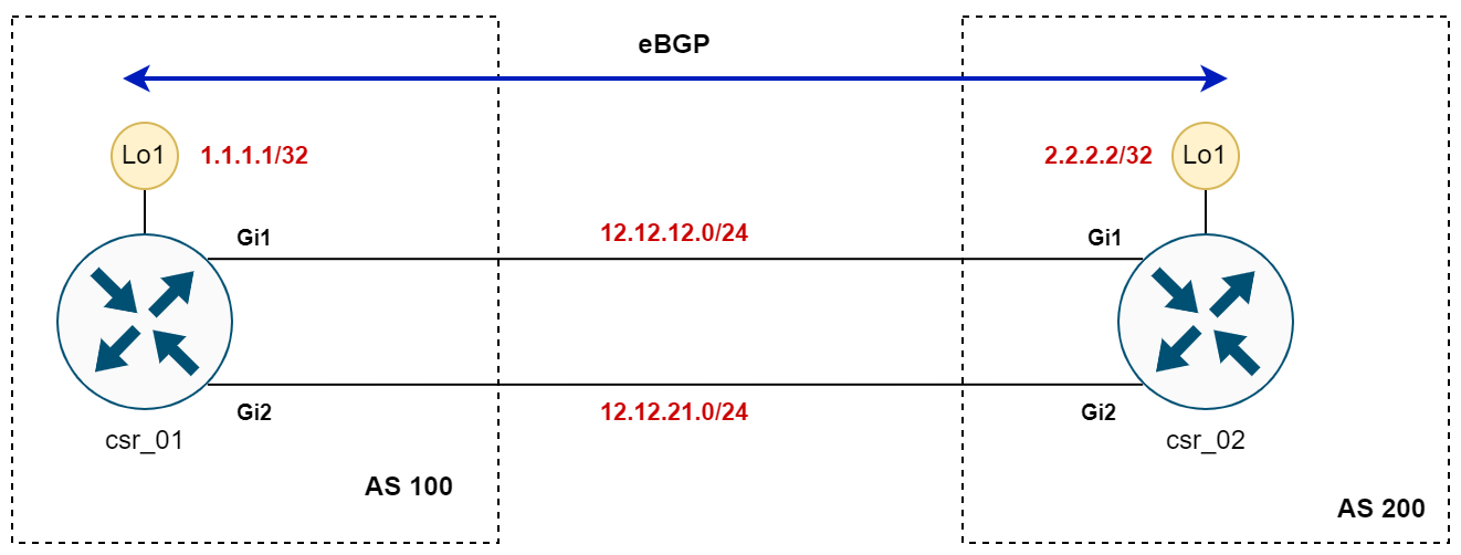
BGP's update-source is a command used to set the source IP address for BGP packets. Normally, BGP uses the IP address of the outgoing interface that's used to connect to a peer. But with update-source, you can specify a different interface, like a loopback interface. This is especially useful because loopback interfaces are more stable – they don't go down unless the router itself goes down. Using a loopback interface as the update source helps keep BGP sessions up and running, even if the direct link between BGP peers goes down, as long as there's another path available in the network.
Imagine you have two routers that are directly connected by two separate links for redundancy. You might wonder whether it's better to establish two separate BGP neighbour relationships or just a single one using the loopback interfaces of the routers. While you could set up two neighbours, it would mean double the work for the routers in maintaining these sessions. The ideal approach is to peer the routers using their loopback IPs, simplifying management and ensuring the neighborship remains stable even if one link goes down.
#csr_01

router bgp 100
 neighbor 2.2.2.2 remote-as 200
#csr_02
router bgp 200
neighbor 1.1.1.1 remote-as 100#csr_01
csr_01#ping 2.2.2.2
Type escape sequence to abort.
Sending 5, 100-byte ICMP Echos to 2.2.2.2, timeout is 2 seconds:
!!!!!
Success rate is 100 percent (5/5), round-trip min/avg/max = 1/1/4 ms#csr_01
csr_01#show ip bgp summary
BGP router identifier 1.1.1.1, local AS number 100
BGP table version is 1, main routing table version 1
Neighbor V AS MsgRcvd MsgSent TblVer InQ OutQ Up/Down State/PfxRcd
2.2.2.2 4 200 0 0 1 0 0 never IdleHowever, if you try this with eBGP, you might notice the session doesn't come up. This is because, by default, as we've seen before, eBGP expects neighbours to be directly connected. Remembering our previous discussion on TTL and direct connections, this setup won't work without adding either the ebgp-multihop or disable-connected-check command.
We don't necessarily need to set the multihop command because TTL 1 is enough for them to connect, as when the router routes the packets from the physical interface to the loopback, it doesn't decrement the TTL value. However, adding the disable-connected-check command is necessary. Let's disable the connected-check and see what happens.
#csr_01

router bgp 100
 neighbor 2.2.2.2 remote-as 200
 neighbor 2.2.2.2 disable-connected-check
router bgp 200
neighbor 1.1.1.1 remote-as 100
neighbor 1.1.1.1 disable-connected-checkBGP router identifier 1.1.1.1, local AS number 100
BGP table version is 1, main routing table version 1
Neighbor V AS MsgRcvd MsgSent TblVer InQ OutQ Up/Down State/PfxRcd
2.2.2.2 4 200 0 0 1 0 0 never IdleEven after adding the disable-connected-check command, you might find the BGP session still won't come up. This is where the update-source command becomes important. Let's dive into why it's needed and what it does.
The update-source command in BGP configuration specifies the source IP address that BGP uses for its packets. By default, BGP uses the IP address of the outgoing interface that connects to its peer. However, when you're trying to establish a session using loopback interfaces, BGP needs to be told explicitly to use a different IP address as the source – in this case, the loopback IP. Here in the Wireshark capture below, you can see that csr_01 is sending the TCP-SYN packet sourced from 12.12.12.1 instead of 1.1.1.1, so csr_02 won't accept the 3-way handshake.
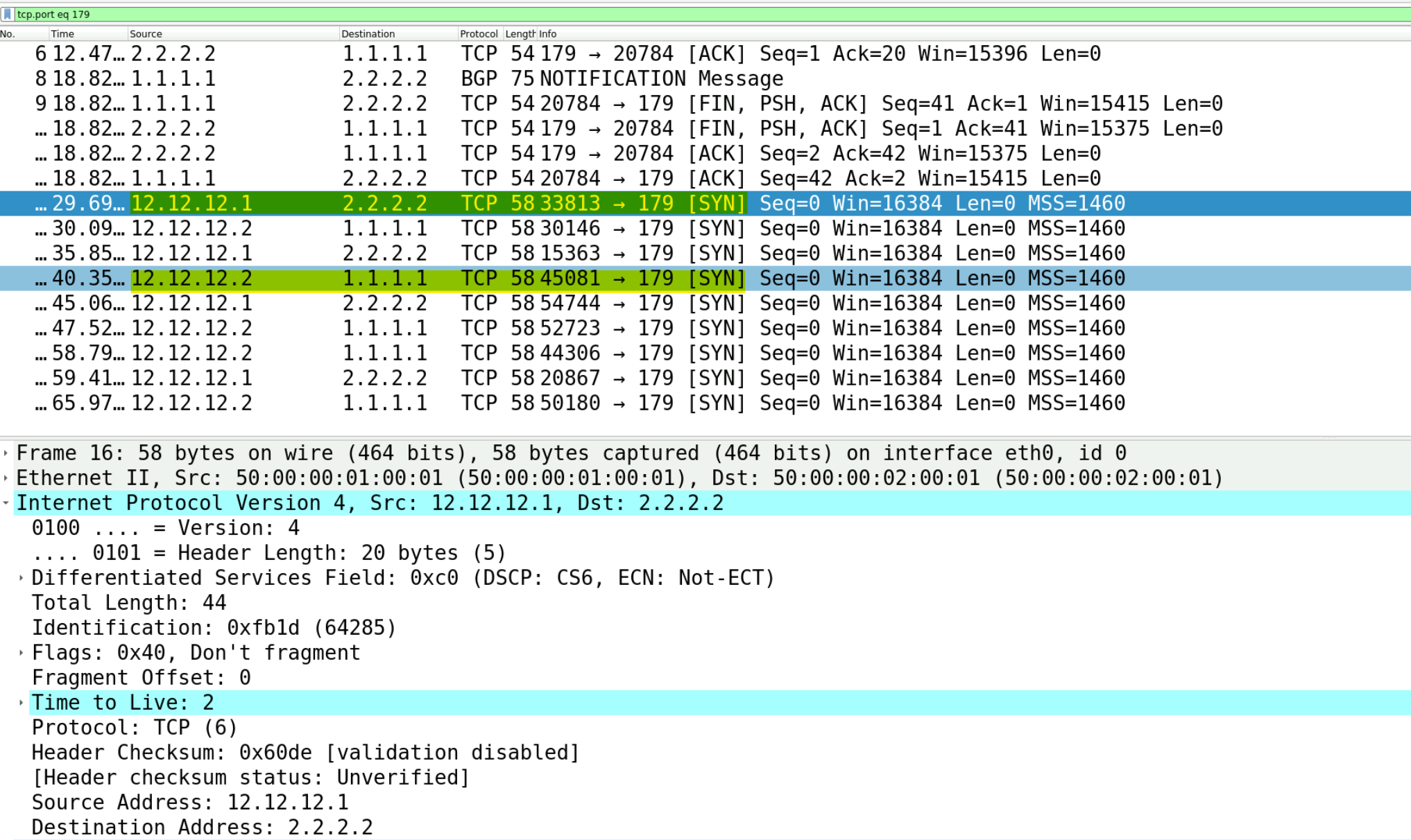
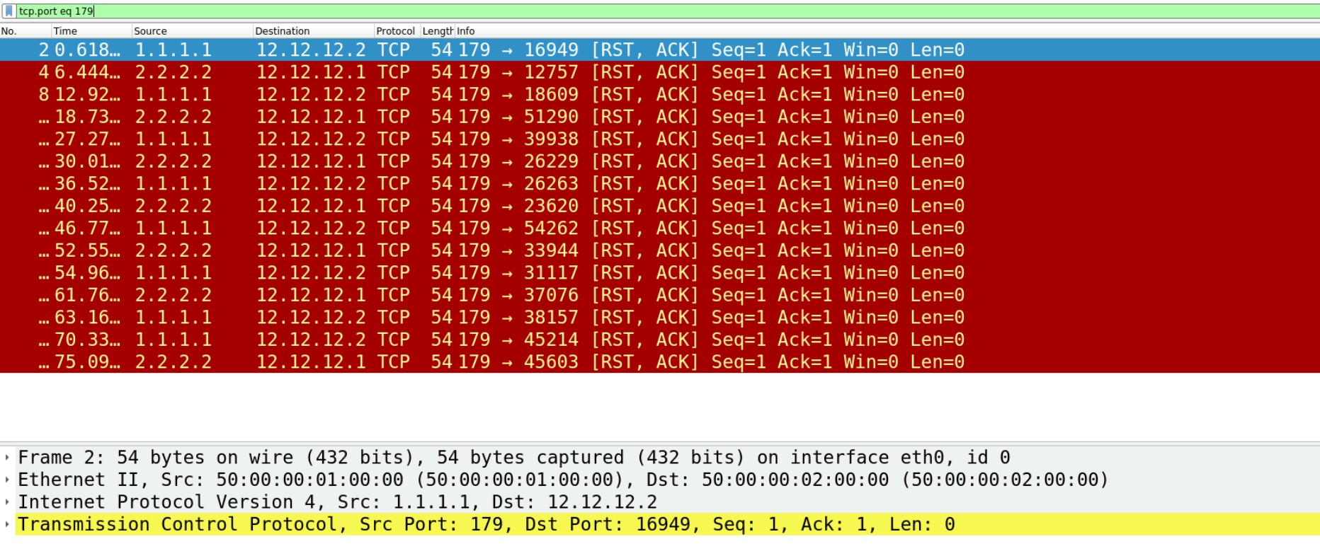
Without specifying update-source, BGP attempts to use the default source IP address (the one on the directly connected interface / outgoing interface), which won't match the expected source IP configured on the peer router. This mismatch prevents the session from being established, as the routers cannot identify each other as the correct BGP peers. Here as you can see in the Wireshark captures, the BGP routers are sending the TCP RST messages. (RST means I don't want to talk to you because your BGP packets are coming from 12.12.12.1 instead of 1.1.1.1)
By configuring update-source to the loopback interface, you ensure that the BGP packets have the correct source IP, matching what's expected on the peer side. This alignment allows the BGP session to be established successfully.
#csr_01

router bgp 100
 bgp log-neighbor-changes
 neighbor 2.2.2.2 remote-as 200
 neighbor 2.2.2.2 disable-connected-check
 neighbor 2.2.2.2 update-source Loopback0
#output
router bgp 200
bgp log-neighbor-changes
neighbor 1.1.1.1 remote-as 100
neighbor 1.1.1.1 disable-connected-check
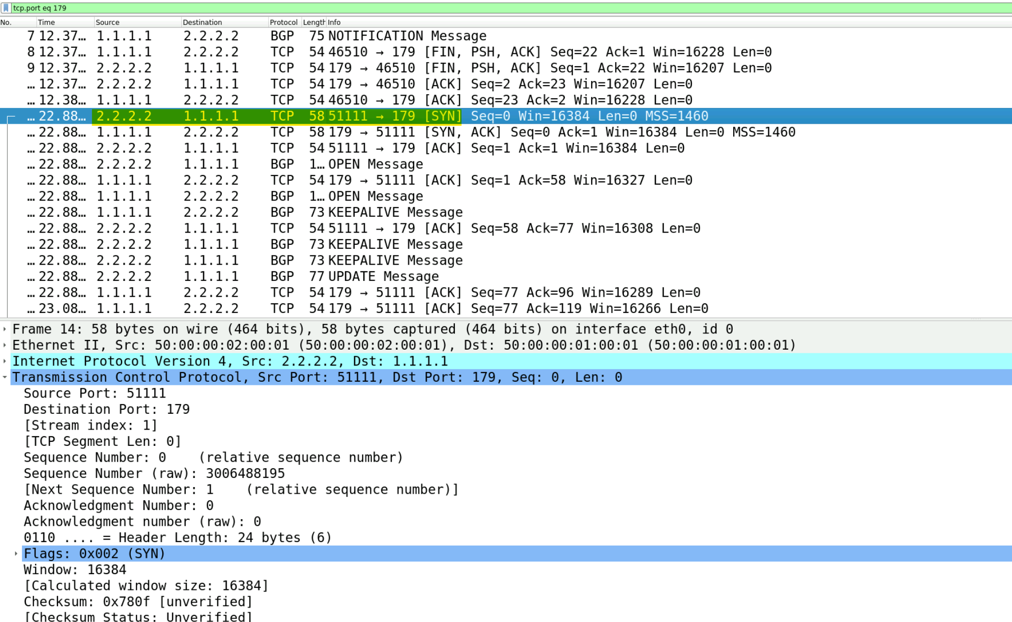
neighbor 1.1.1.1 update-source Loopback0Here, you can see in the capture that both routers are using their loopback IP for communication.
*Mar 29 20:38:19.474: %BGP-5-ADJCHANGE: neighbor 2.2.2.2 Up

BGP router identifier 1.1.1.1, local AS number 100
BGP table version is 1, main routing table version 1

Neighbor        V           AS MsgRcvd MsgSent   TblVer  InQ OutQ Up/Down  State/PfxRcd
2.2.2.2         4          200       5       5        1    0    0 00:01:41        0
To close up, The ebgp-multihop command allows BGP sessions to connect through multiple routers, not just the ones directly connected. It's used when BGP peers are several hops away from each other. The update-source command specifies which IP address BGP should use to identify itself to its peer, making sure the session can be established correctly even when using non-direct paths.
IGP Use Case with BGP
In our previous scenario, we successfully set up eBGP using loopback addresses. But how do the routers know how to reach each other's loopback addresses? This is where an Interior Gateway Protocol (IGP) like OSPF or static routing comes into play.