
In the previous post, we covered the basics of multicast. In this post, we will focus on IGMP, Internet Group Management Protocol.
Just as a quick recap, in multicast, the source application (sender) sends multicast traffic to a multicast group address. Somewhere in the network, a receiver wants that traffic stream, so the receiver needs a way to signal that interest.
The router closest to the source is called the First Hop Router (FHR), and the router closest to the receiver is called the Last Hop Router (LHR). Between these two points, the multicast network, meaning all multicast-enabled routers, needs to build a loop-free tree that connects the sender to all interested receivers. IGMP plays a key role in making that happen.

As always, if you find this post helpful, press the ‘clap’ button. It means a lot to me and helps me know you enjoy this type of content.
IGMP Introduction
IGMP is the protocol used by receivers to signal their interest in multicast traffic. When a host wants to receive a multicast stream, it sends an IGMP Membership Report, also known as an IGMP join, to the multicast group address.

The last hop router or LHR sees this message and learns that there is an interested receiver on that local segment. Once the last hop router learns about interested receivers through IGMP, PIM (Protocol-Independent Multicast) is then used between routers to build the multicast forwarding path back toward the source, which we will look at in detail in the next post. For now, let's focus on IGMP only.
IGMP has evolved over time, and there are three main versions you will see in networks today.
- IGMPv1 is the original version. It allows hosts to join a multicast group but does not support leaving a group explicitly. Routers rely on timeouts to figure out when receivers are no longer interested.
- IGMPv2 improves on this by adding an explicit leave message. This allows hosts to signal when they are done with a multicast group, which helps routers stop forwarding traffic sooner.
- IGMPv3 adds support for Source Specific Multicast. With IGMPv3, receivers can specify not only the multicast group they want to join, but also which source they want to receive traffic from.
IGMPv1 is the original version of the Internet Group Management Protocol. It allows hosts to join a multicast group by sending membership reports, but it has no explicit way for a host to leave a group. Routers rely on periodic queries and timers to decide whether receivers are still interested in the multicast traffic.
IGMPv1 is considered outdated today. IGMPv2 is enabled by default on most devices, and that is the version we will focus on in this post.
IGMPv2
IGMPv2 builds on the basics of IGMPv1 and makes multicast behavior more efficient. Hosts still use membership reports to join a multicast group, but IGMPv2 adds an explicit leave message so receivers can signal when they are no longer interested. This allows the last hop router to stop forwarding multicast traffic sooner instead of waiting for timers to expire, which reduces unnecessary traffic on the local segment.
IGMPv2 Message
IGMP messages are carried inside IP packets using IP protocol number 2. They are always sent with a TTL of 1, which means they never leave the local network segment, and they include the IP Router Alert option so routers process them. Similar to ICMP, IGMP does not use TCP or UDP. It runs directly on top of IP as its own protocol.
IGMPv2 messages are simple and fixed to the first 8 bytes. Each message contains a Type, Max Response Time, Checksum, and Group Address.
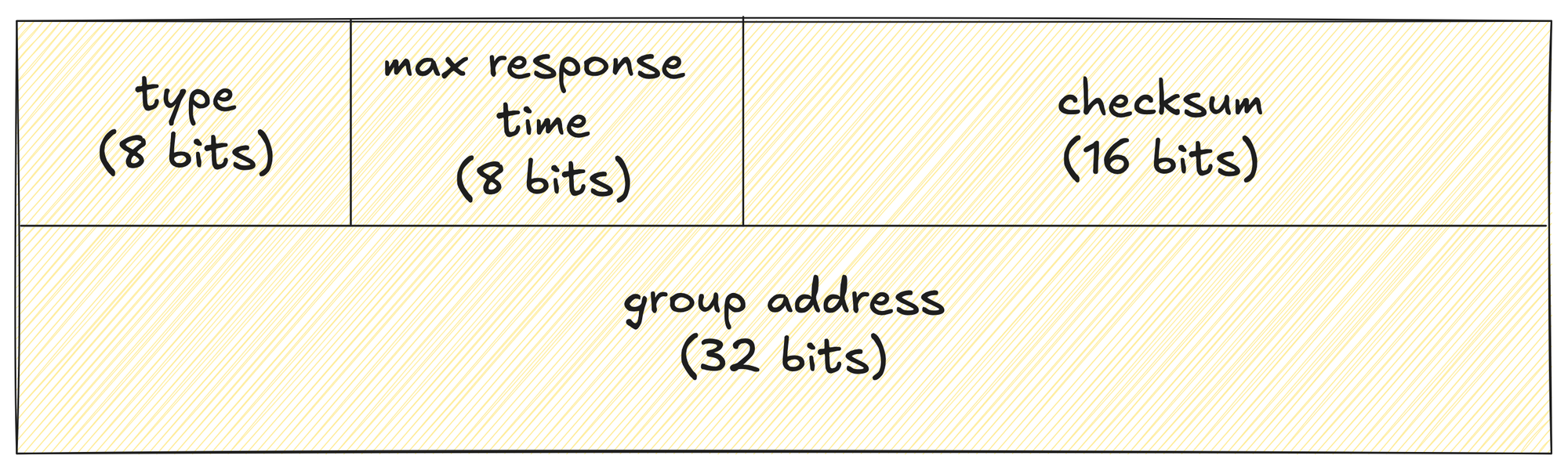
- The Type field defines what kind of IGMP message it is, such as a Membership Query, Membership Report, or Leave Group message.
- 0x11 - Membership Query. There are two sub-types of Membership Query messages.
- General Query, used to learn which groups have members on an
attached network. - Group-Specific Query, used to learn if a particular group
has any members on an attached network.
- General Query, used to learn which groups have members on an
- 0x16 - Version 2 Membership Report
- 0x17 - Leave Group
- 0x12 - Version 1 Membership Report
- 0x11 - Membership Query. There are two sub-types of Membership Query messages.
- The Max Response Time field is only used in Query messages and controls how long a receiver can wait before replying.
- The Checksum is used for basic integrity checking of the IGMP message.
- The Group Address identifies which multicast group the message applies to, or is set to zero in the case of a general query.
IGMP Example
Here we have a single router, and we enable PIM on the interfaces (don't worry about the configs for now) connected to both the sender segment and the receiver segment. As soon as PIM is enabled, IGMP is also enabled automatically.
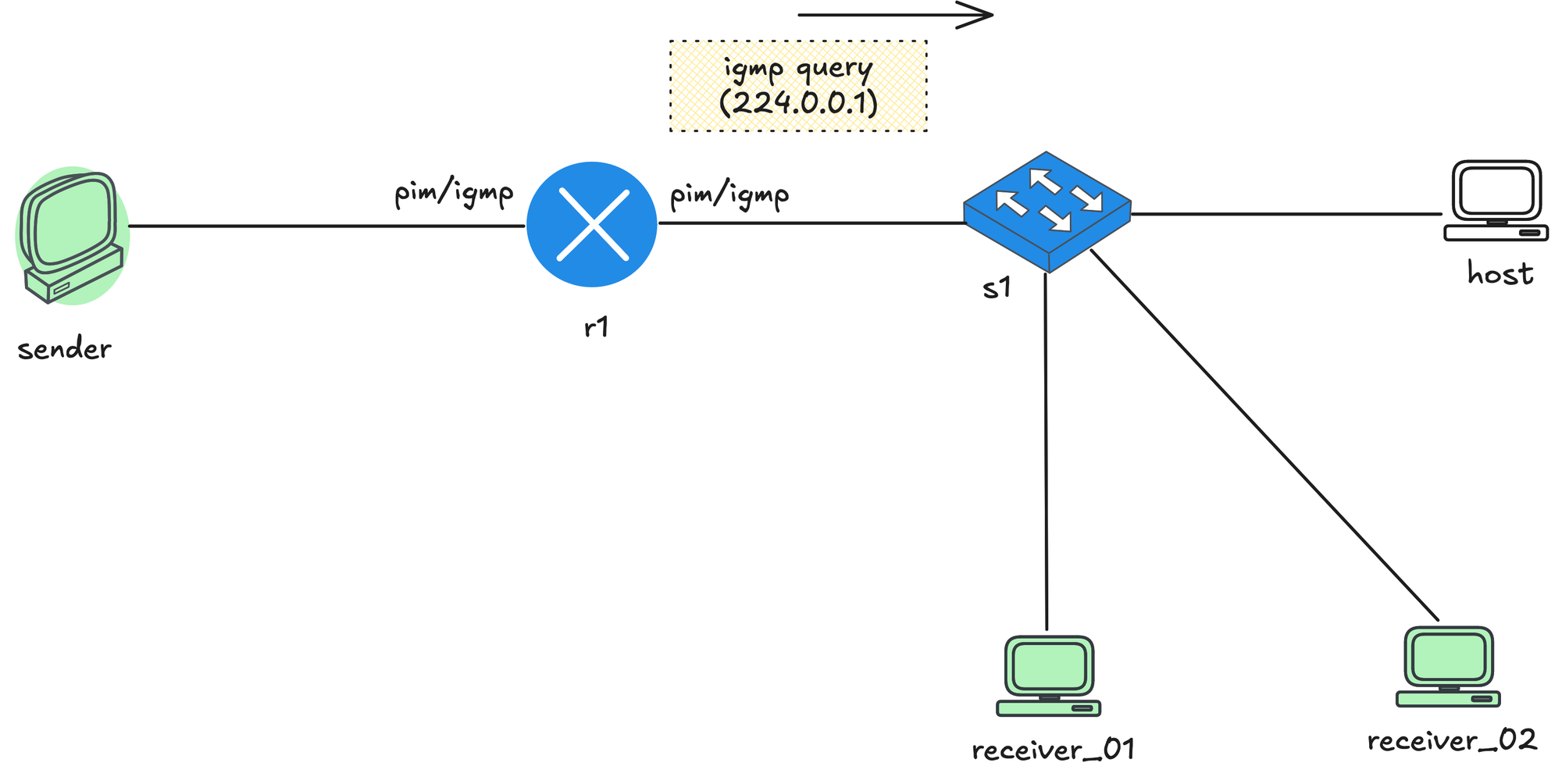
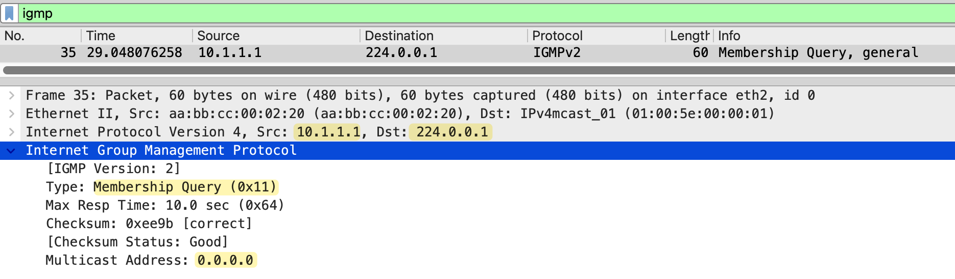
The router immediately starts sending IGMP General Membership Queries out of both interfaces, asking if there are any interested receivers on those segments. The source IP of the IGMP query is the router’s own interface IP address, and the destination IP is the all systems multicast address 224.0.0.1.
The IGMP message itself has the Multicast Address field set to 0.0.0.0, which indicates the query is asking about all multicast groups on that segment.
Let's say now the sender starts sending multicast traffic to the group address 239.1.1.1. The sender does not know who the receivers are or if anyone is listening. It simply sends traffic to the multicast group.
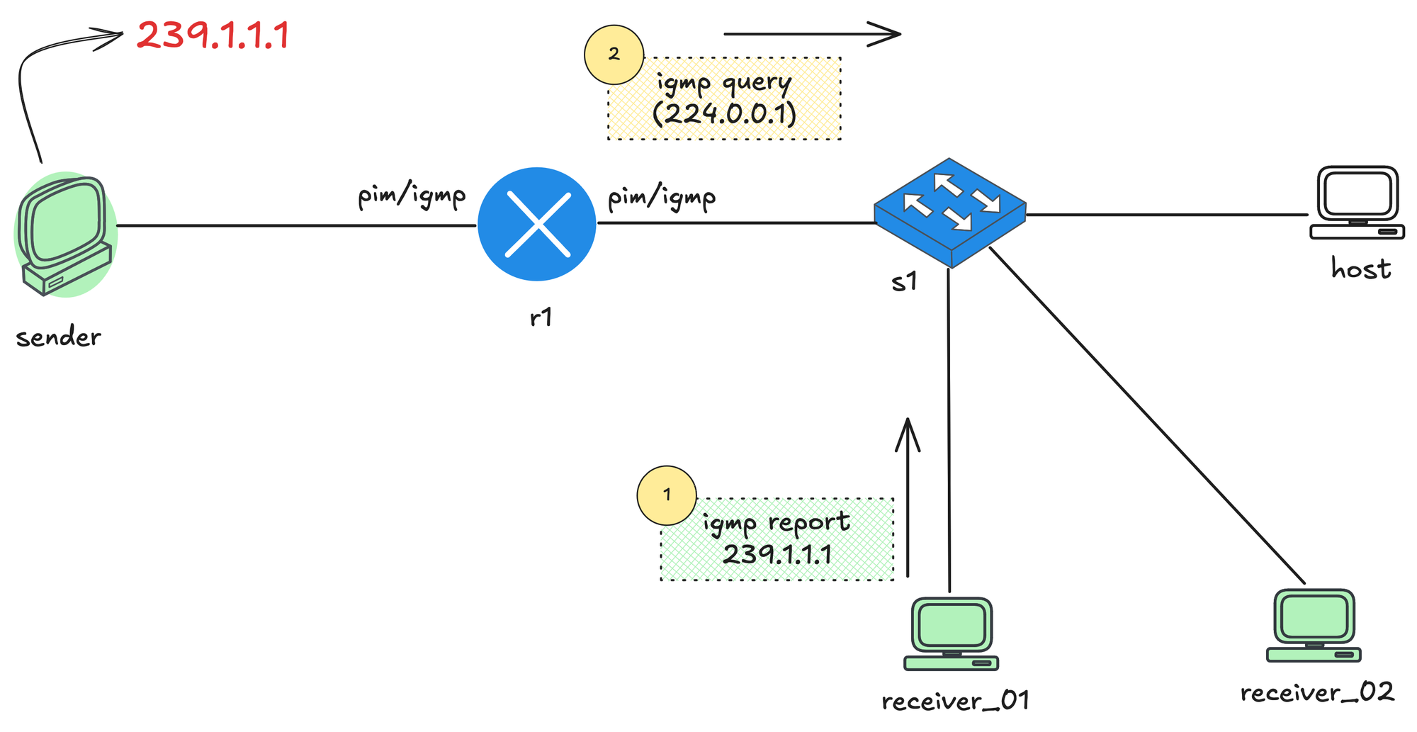
receiver_01 decides it wants to receive this stream. To do that, it sends an IGMP Membership Report for 239.1.1.1. This message is sent toward the local network and reaches the last hop router, r1. When r1 receives this IGMP report, it learns that there is at least one interested receiver for the multicast group 239.1.1.1 on that segment. From this point on, r1 knows it should allow multicast traffic for that group to be forwarded toward receiver_01.
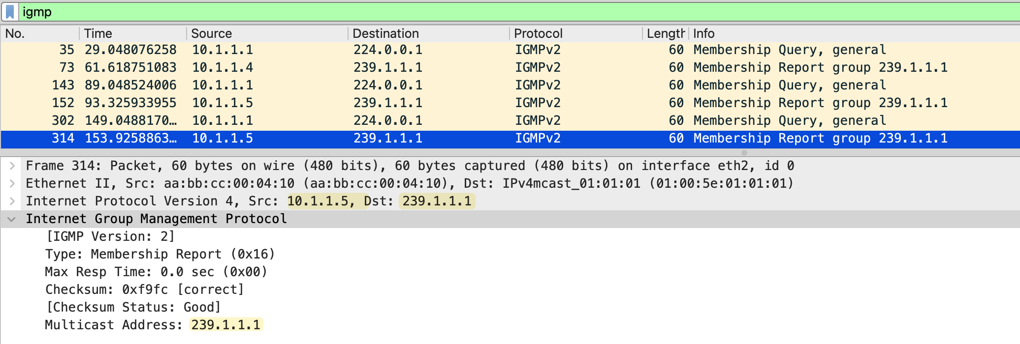
The source IP address of the report is the unicast IP address of the receiver (10.1.1.5 in this example). The destination IP address is the multicast group address, which in this case is 239.1.1.1. Inside the IGMP report itself, the Group Address field is also set to 239.1.1.1, as shown in the packet capture below.
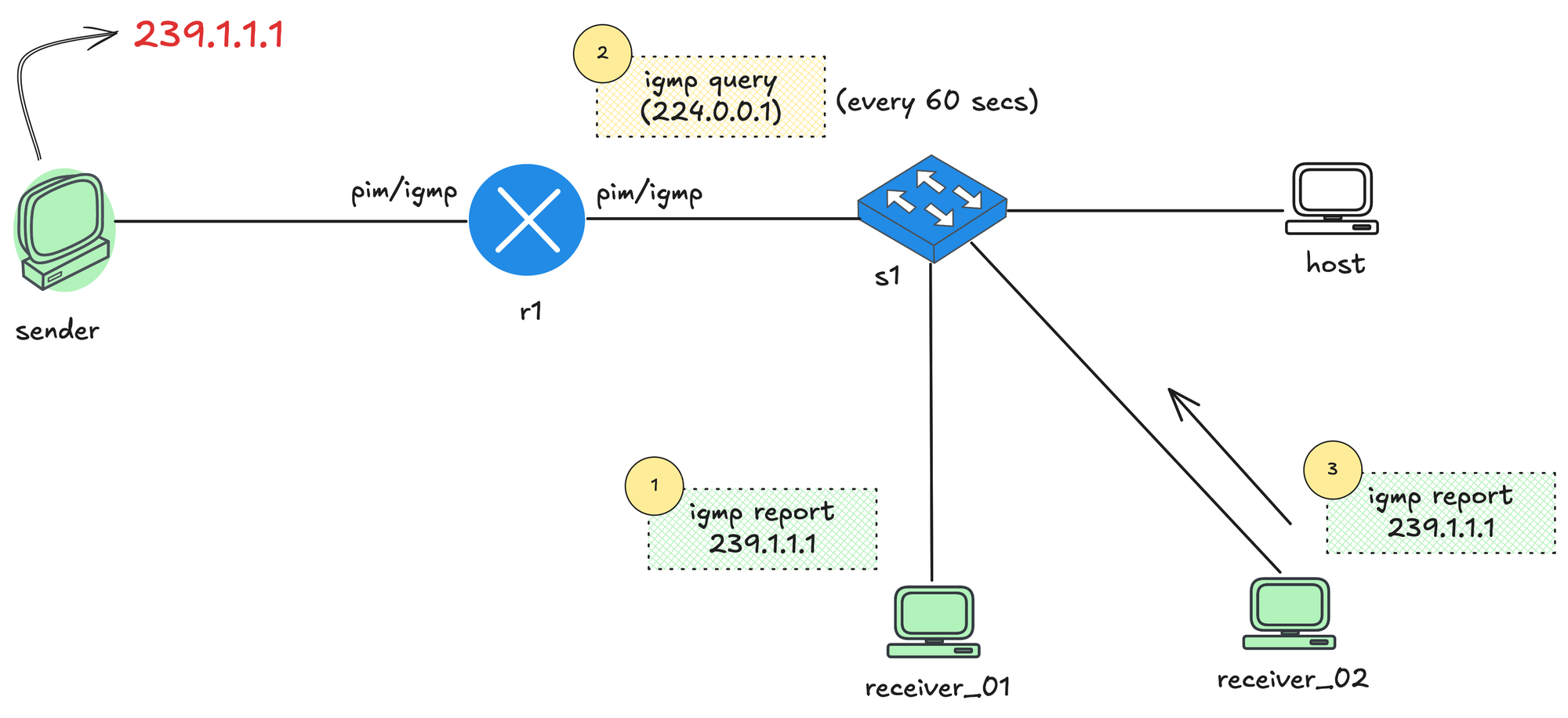
To keep track of active receivers, r1 periodically sends IGMP Queries to the address 224.0.0.1, which represents all systems on the local segment. Any receiver that still wants multicast traffic responds with another IGMP report. This process allows the router to continuously verify which multicast groups still have interested receivers.
When receiver_02 also joins the multicast group, it sends an IGMP Membership Report for 239.1.1.1, which is received by r1 as well.
Later, when r1 sends an IGMP Query to 224.0.0.1, both receiver_01 and receiver_02 receive the query. Instead of replying immediately, each receiver starts a random report delay timer (less than the Max Response Time from the membership query). This is done to avoid all receivers responding at the same time, which would not scale if there were hundreds of hosts. If you jog your memory, this random delay comes from a field in the IGMP Query message itself. In the earlier packet capture, we saw the Max Response Time set to 10 seconds by default, which means receivers will pick a random delay somewhere below those 10 seconds before sending their report.
In this example, let's say receiver_01 sets its timer to 2 seconds and receiver_02 sets its timer to 7 seconds. After 2 seconds, receiver_01 sends an IGMP Membership Report for 239.1.1.1. That report is received by r1 and also seen by receiver_02. Because receiver_02 has already heard a report for the same multicast group on the segment, it suppresses its own report and does not send anything when its timer expires. This report suppression mechanism is to keep IGMP traffic low while still allowing the router to learn that there are active receivers on the network.
The router periodically sends IGMP General Membership Queries to check if receivers are still interested. As long as reports continue to arrive, the router keeps forwarding the multicast stream.
IGMP Leave Message
When a host no longer wants to receive a multicast stream, it sends an IGMP Leave Group message (only in IGMPv2). The source IP of this message is the unicast IP of the host, and the destination IP is the all routers multicast address 224.0.0.2.
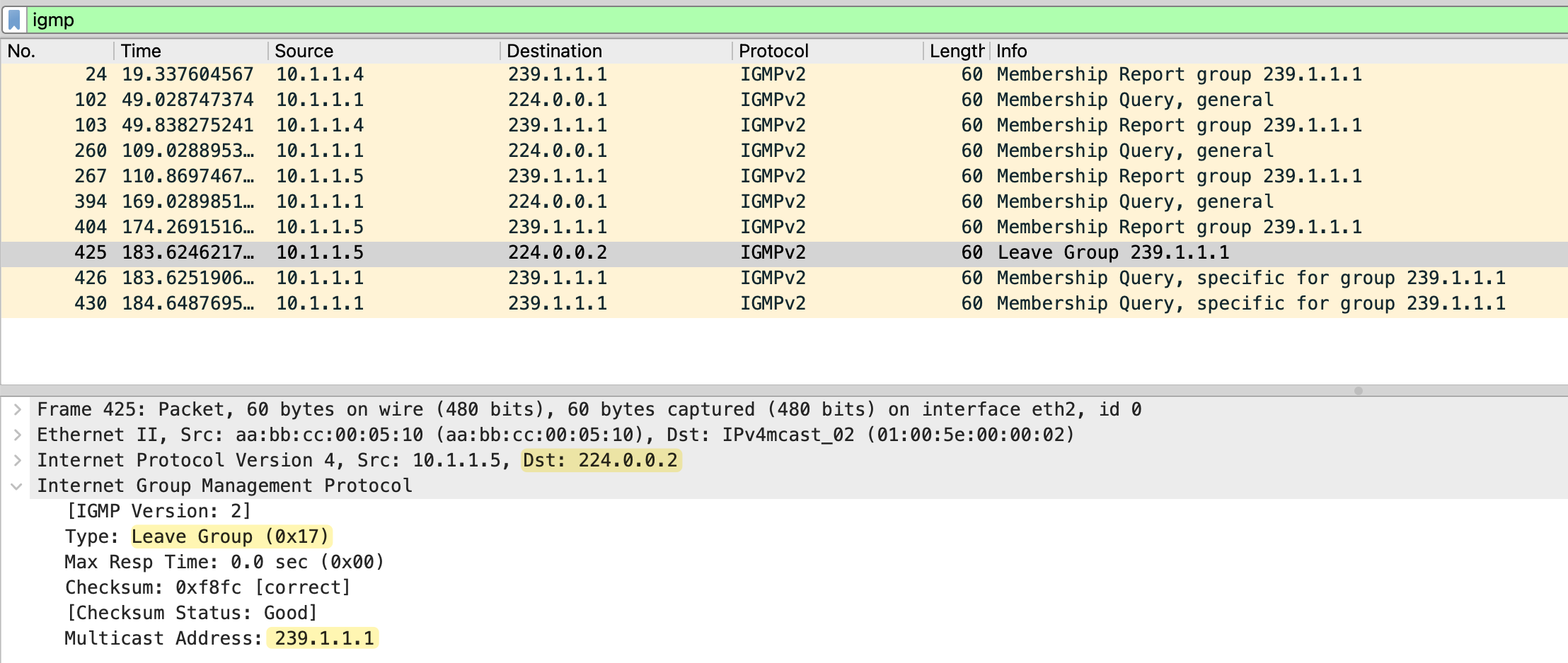
In the IGMP message itself, the Type is set to 0x17 (Leave Group), and the Group Address field is set to the multicast group being left, which in this case is 239.1.1.1.
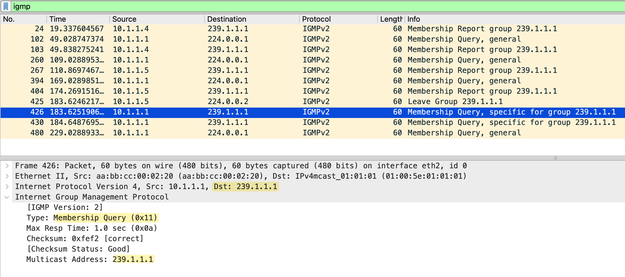
When the last hop router receives this leave message, it does not immediately stop forwarding traffic. Instead, it sends a Group Specific Membership Query for 239.1.1.1. This query is sent to the multicast group address 239.1.1.1 and uses the Membership Query (0x11) type.
The router sends two group-specific queries, one second apart, and if no membership report is received within 0.5 seconds after the last query, the router removes the multicast group from that interface.
IGMP Snooping
So far, we have focused on how IGMP works between hosts and routers. IGMP snooping is a switch feature that listens to IGMP messages and uses them to control how multicast traffic is forwarded at Layer 2. Instead of flooding multicast traffic out of all ports, a switch with IGMP snooping enabled can forward traffic only to the ports where interested receivers exist.
So far, we have not talked about how switches handle multicast traffic. With unicast traffic, switches work by learning source MAC addresses and build a MAC address table. When a unicast frame arrives, the switch looks up the destination MAC and forwards the frame out of a single port. If the MAC is unknown, the frame is flooded until the switch learns where that device lives.
Multicast introduces a challenge for switches. Multicast frames use a destination MAC address that represents a group, not a single device. By default, the switch has no idea which ports actually have interested receivers, so the safest option is to flood multicast traffic out of all ports in the VLAN. This works, but it is inefficient and can look very similar to broadcast traffic.
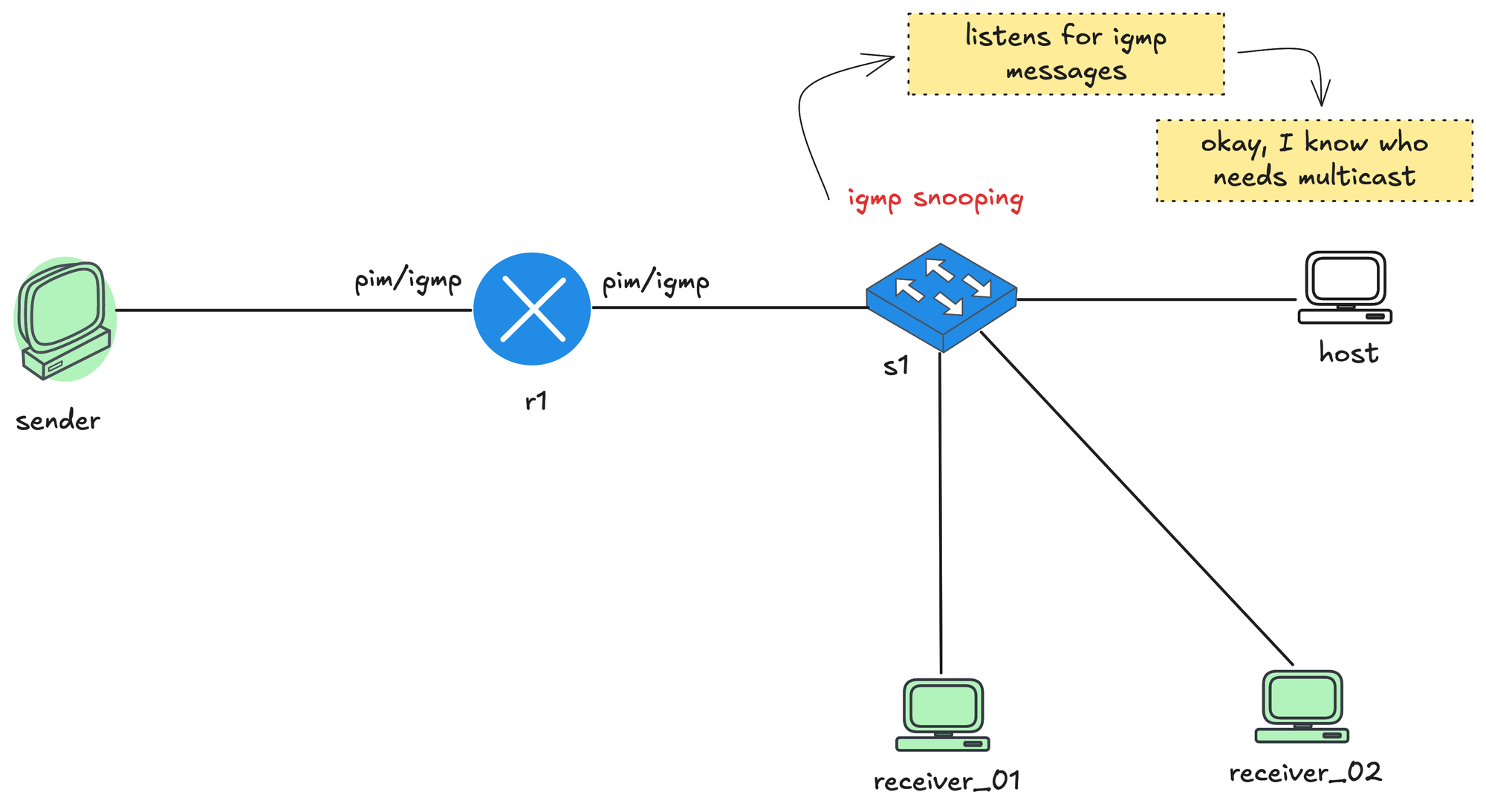
When IGMP snooping is enabled, the switch listens to IGMP messages that pass through it. It watches for IGMP membership reports from receivers and notes which ports those reports came in on. From this, the switch builds a table that maps multicast groups to specific switch ports. When multicast traffic starts flowing, the switch no longer floods it everywhere. Instead, it forwards the multicast frames only out of the ports where it has seen receivers join that multicast group. Ports with no interested receivers do not get the traffic. It also learns which port is connected to the routers by listening on IGMP and PIM messages.
The switch also listens for IGMP leave messages. When a receiver leaves a group, the switch updates its table and stops forwarding multicast traffic to that port if no other receivers are present. This keeps multicast traffic contained and prevents it from behaving like broadcast traffic on the LAN.
IGMP Snooping Report and Leave Messages
Remember earlier we talked about how, when a router sends an IGMP query, only one receiver replies due to the report suppression mechanism. This behavior creates a challenge for the switch. When multiple receivers are connected behind a switch and a router sends an IGMP query, the receivers use the report suppression mechanism. One receiver sends the first membership report, and the others suppress theirs.
With this approach, the switch would not know which ports actually have active receivers for the multicast group, and it would have no way to build an accurate multicast forwarding table. To solve this, the switch forwards the first IGMP membership report toward the router, but it does not flood that report to other hosts. The other receivers on different ports still let their delay timers expire and then send their own reports. The switch sees these reports locally and learns that there are multiple interested ports for the same multicast group, even though only one report was forwarded upstream to the router.
Similarly, when the switch receives an IGMP Leave message on a port, the switch only forwards a leave message to the router when there are no interested receivers left on the segment. For example, if two receivers are joined to the same multicast group and one of them sends a leave, the switch does not forward that leave to the router. Only when the last receiver leaves does the switch forward the leave message upstream.
Also worth mentioning that when the switch receives IGMP leave message on a port, it does not immediately assume that there are no receivers left on that port. It sends an IGMP query out of that same port to check if there are any other interested receivers. This is important in cases where multiple hosts exist behind a single port or when that port connects to another switch.
Multicast Lab
Now the fun part, let’s lab this out and look at some very basic configurations. For this example, I am going to use Cisco IOL images with Netlab and Containerlab, but you can use EVE-NG, GNS3, or whatever you prefer. I will attach the Netlab topology file below so you can spin up the entire pre configured lab with a single command.
I have covered Netlab in detail before, so feel free to check that out as well if you want some background before getting started.

Before we jump into the lab, please note that we will also use Cisco nodes as the sender and receiver. I know that might sound a bit odd at first. The reason for this is that Cisco routers make it very easy to simulate sending multicast traffic and joining multicast groups using a single command. This makes them perfect for lab work.
The sender and receiver Cisco nodes we use will not participate in any routing. We can disable IP routing completely and configure a default gateway, which effectively turns them into end devices for the purpose of this lab.
no ip routing
ip default-gateway x.x.x.x
Initial Configuration
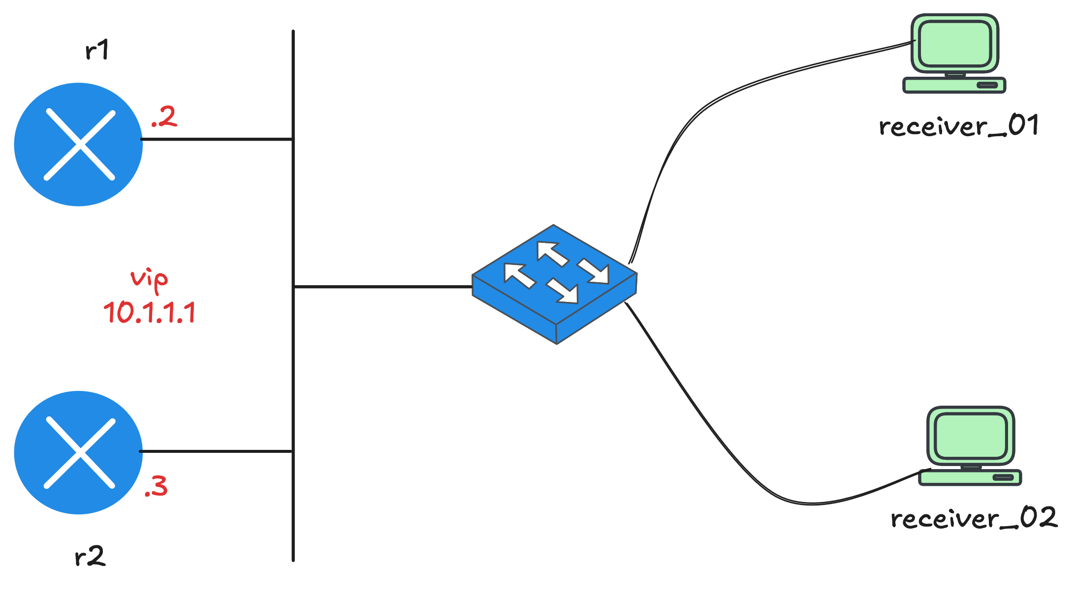
This example is based on the topology shown below. We have a single router r1 in the middle of the network. On the left side, a single sender is directly connected to r1. On the right side, r1 connects to a switch, s1, which in turn connects to three hosts.
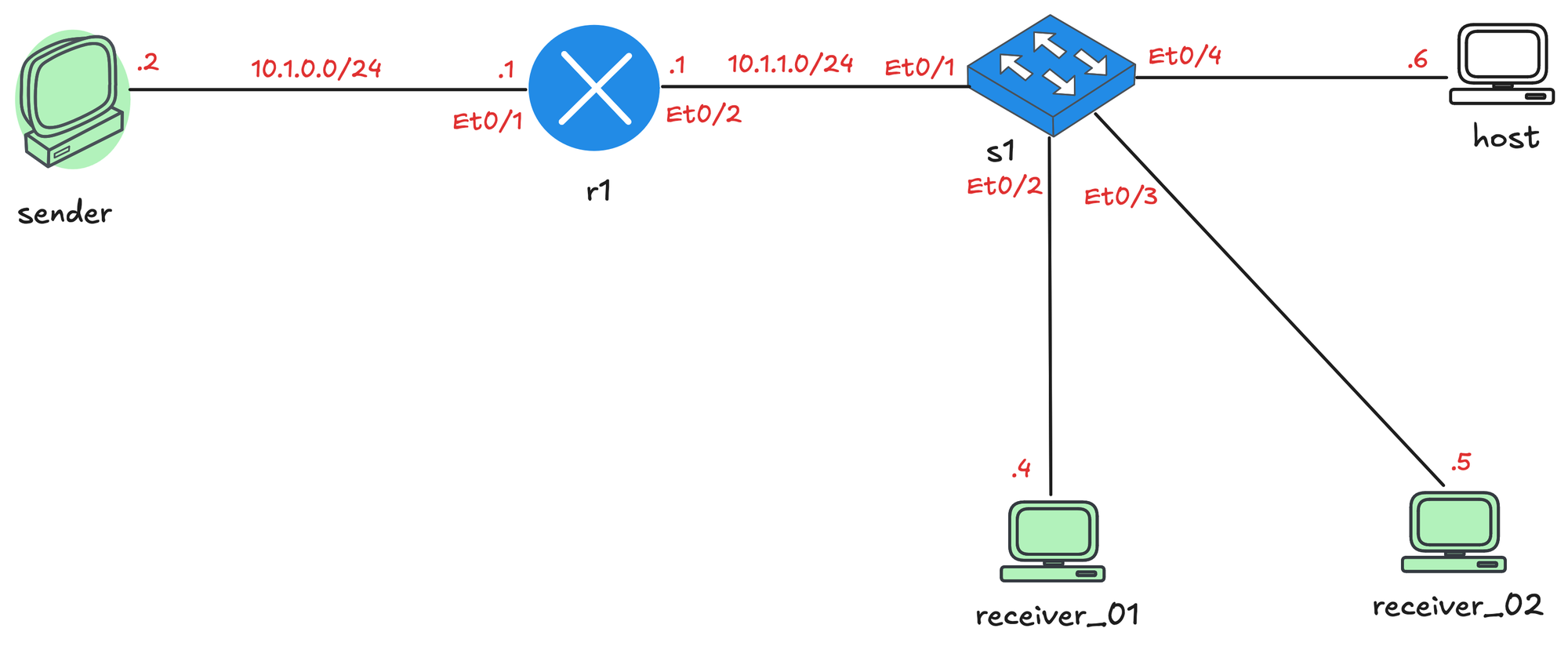
Out of those three hosts, two will act as multicast receivers in this lab. The third host is just there and does absolutely nothing.
As mentioned earlier, the sender and receivers do not participate in any routing (even though they are Cisco routers). IP routing is disabled on those nodes, and r1 is configured as their default gateway. At this point, we already have full unicast reachability between the sender and the receivers, which gives us a clean baseline before introducing multicast.
sender#ping 10.1.1.5
Type escape sequence to abort.
Sending 5, 100-byte ICMP Echos to 10.1.1.5, timeout is 2 seconds:
!!!!!
Success rate is 100 percent (5/5), round-trip min/avg/max = 1/1/2 ms
Enable IGMP
The first thing we will do is disable Auto RP on r1 by running the no ip pim autorp command. Do not worry too much about this for now, we will cover Auto RP later in the series. If we leave this enabled, we will see a lot of extra messages in the debugs, which will just clutter the output and make things harder to follow.
r1#show run | sec auto
no ip pim autorp
Next, we will configure multicast routing globally and enable PIM on both interfaces of r1. Enabling PIM on an interface also enables IGMP on that interface. Again, do not worry about PIM at this stage. Our full focus here is IGMP, and enabling PIM is the only way to turn on IGMP on the interfaces facing the sender and the receivers.
#r1

ip multicast-routing
!
interface Ethernet0/1
 description r1 -> sender
 ip address 10.1.0.1 255.255.255.0
 ip pim dense-mode
!
interface Ethernet0/2
 description r1 -> [receiver_01,receiver_02,host,s1]
 ip address 10.1.1.1 255.255.255.0
 ip pim dense-mode
!
As soon as we enable PIM, IGMPv2 is automatically enabled on those interfaces. The router immediately starts sending IGMP General Membership Query messages out of the interfaces, effectively asking, “Is there any interested receiver on this segment?” You can enable debugging on r1 to see these messages going out, by default the router sends queries every 60 seconds.
r1#terminal monitor
r1#debug ip igmp
r1#
*Jan 23 21:37:48.667: Send v2 general Query on Ethernet0/1
*Jan 23 21:37:48.934: Send v2 general Query on Ethernet0/2
r1#
r1#
*Jan 23 21:38:48.667: Send v2 general Query on Ethernet0/1
*Jan 23 21:38:48.933: Send v2 general Query on Ethernet0/2You can also check the IGMP state on r1 using show ip igmp interface command. This command shows that IGMP is enabled on the interfaces, that IGMPv2 is in use, and shows key timers like the 60 second query interval and the 10 second max response time. It also tells us which router is acting as the IGMP querier and multicast designated router. In this lab, r1 is the only router on the segments, so it performs both roles and is responsible for sending IGMP queries.
r1#show ip igmp interface
Ethernet0/1 is up, line protocol is up
  Internet address is 10.1.0.1/24
  IGMP is enabled on interface
  Current IGMP host version is 2
  Current IGMP router version is 2
  IGMP query interval is 60 seconds
  IGMP configured query interval is 60 seconds
  IGMP robustness-variable is 2
  IGMP querier timeout is 120 seconds
  IGMP configured querier timeout is 120 seconds
  IGMP max query response time is 10 seconds
  Last member query count is 2
  Last member query response interval is 1000 ms
  Inbound IGMP access group is not set
  IGMP activity: 0 joins, 0 leaves
  Multicast routing is enabled on interface
  Multicast TTL threshold is 0
  Multicast designated router (DR) is 10.1.0.1 (this system)
  IGMP querying router is 10.1.0.1 (this system)
  No multicast groups joined by this system

Ethernet0/2 is up, line protocol is up
  Internet address is 10.1.1.1/24
  IGMP is enabled on interface
  Current IGMP host version is 2
  Current IGMP router version is 2
  IGMP query interval is 60 seconds
  IGMP configured query interval is 60 seconds
  IGMP robustness-variable is 2
  IGMP querier timeout is 120 seconds
  IGMP configured querier timeout is 120 seconds
  IGMP max query response time is 10 seconds
  Last member query count is 2
  Last member query response interval is 1000 ms
  Inbound IGMP access group is not set
  IGMP activity: 0 joins, 0 leaves
  Multicast routing is enabled on interface
  Multicast TTL threshold is 0
  Multicast designated router (DR) is 10.1.1.1 (this system)
  IGMP querying router is 10.1.1.1 (this system)
  No multicast groups joined by this system
IGMP Snooping Configuration
There is nothing to configure because IGMP snooping is enabled by default on Cisco switches.
s1#show ip igmp snooping
Global IGMP Snooping configuration:
-------------------------------------------
IGMP snooping Oper State     : Enabled
IGMPv3 snooping              : Enabled
Report suppression           : Enabled
TCN solicit query            : Disabled
Robustness variable          : 2
Last member query count      : 2
Last member query interval   : 1000
Check TTL=1                  : No
Check Router-Alert-Option    : No
Send Multicast Traffic
To generate multicast traffic from the sender, which is a Cisco device, we can simply use the ping command followed by a multicast IP address. In this example, I will use 239.1.1.1 as the multicast group.
sender#ping
Protocol [ip]:
Target IP address: 239.1.1.1
Repeat count [1]: 200
Datagram size [100]:
Timeout in seconds [2]:
Extended commands [n]:
Sweep range of sizes [n]:
Type escape sequence to abort.
Sending 200, 100-byte ICMP Echos to 239.1.1.1, timeout is 2 seconds:
......
Reply to request 6 from receiver_01 (10.1.1.4), 2 ms
Reply to request 7 from receiver_01 (10.1.1.4), 1 ms
Reply to request 8 from receiver_01 (10.1.1.4), 1 ms
Reply to request 9 from receiver_01 (10.1.1.4), 1 ms
Reply to request 10 from receiver_01 (10.1.1.4), 1 ms
Reply to request 11 from receiver_01 (10.1.1.4), 2 ms
At first, you will not see any replies. As soon as a receiver subscribes to the multicast group, replies start to appear. To make a Cisco router act as a receiver, you can join the multicast group directly on an interface using the following command.
Join Multicast Group
receiver_01(config)#interface et0/1
receiver_01(config-if)#ip igmp join-group 239.1.1.1
Now that we have a sender sending multicast traffic and receiver_01 joining the group, let’s look at some debug output, starting with r1.
Received v2 Report on Ethernet0/2 from 10.1.1.4 for 239.1.1.1
Received Group record for group 239.1.1.1, mode 2 from 10.1.1.4 for 0 sources
On r1, you will see IGMP General Membership Queries being sent out as soon as PIM was enabled on the interfaces. When receiver_01 joins the multicast group, it sends an IGMP Membership Report, which is then received and processed by r1.
On receiver_01, the debug output shows the membership report being generated and sent when the join group command is applied.
receiver_01(config-if)#ip igmp join-group 239.1.1.1
receiver_01(config-if)#
Registering IGMP with ipmulticast GIR
WAVL Insert group: 239.1.1.1   interface: Ethernet0/1 Successful
Send v2 Report for 239.1.1.1 on Ethernet0/1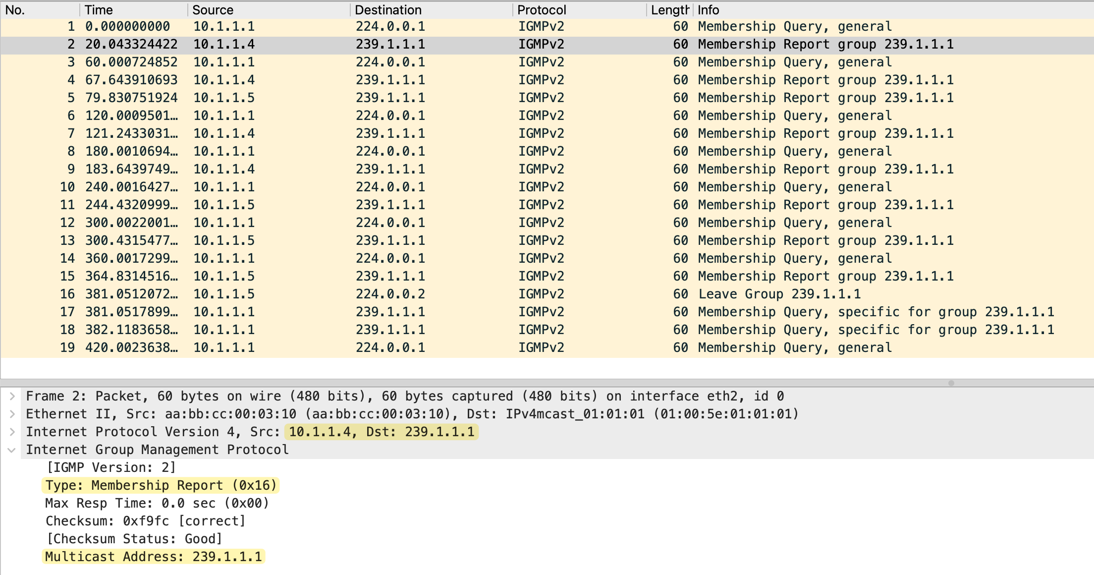
You can also see similar IGMP related debug messages on s1, which confirms that the switch is seeing the IGMP traffic.
IGMPSN: Received IGMPv2 message for group 239.1.1.1 received on Vlan 100, port Et0/2
IGMPSN: router: port Et0/2 is not a router port on Vlan 100
IGMPSN: group: Skip client info adding - ip 10.1.1.4, port_id Et0/2, on vlan 100
Now let’s also have receiver_02 join the multicast group. This lets us observe both the IGMP report delay behavior and IGMP snooping.
receiver_02(config)#interface et0/1
receiver_02(config-if)#ip igmp join-group 239.1.1.1
When receiver_02 joins, both receivers will send IGMP membership reports to the query from r1. This happens because the switch receives the first report and forwards it to the router, but it does not forward that report to the other receivers. Since the receivers do not hear each other’s reports, their delay timers expire, and they each send their own report.
#receiver_01

Received v2 Query on Ethernet0/1 from 10.1.1.1
Set report delay time to 1.2 seconds for 239.1.1.1 on Ethernet0/1
Send v2 Report for 239.1.1.1 on Ethernet0/1
#receiver_02
Received v2 Query on Ethernet0/1 from 10.1.1.1
Set report delay time to 2.0 seconds for 239.1.1.1 on Ethernet0/1
Send v2 Report for 239.1.1.1 on Ethernet0/1From the router's point of view, nothing changes. The router only ever sees a single report and simply knows that there is interest in the multicast group on that segment.
Received v2 Report on Ethernet0/2 from 10.1.1.4 for 239.1.1.1As you can see in the debug output above, r1 only sees a membership report from receiver_01. This is because receiver_01 set a shorter report delay time to 1.2 seconds, and sent its report first.
On the switch, we can see that it learns that multiple interfaces are interested in the same multicast group and adds those interfaces to the forwarding entry for that group. This is how IGMP snooping builds accurate multicast forwarding state at Layer 2.
s1#show ip igmp snooping groups
Flags: I -- IGMP snooping, S -- Static, P -- PIM snooping, A -- ASM mode

Vlan      Group/source             Type        Version     Port List
-----------------------------------------------------------------------
100       239.1.1.1                I           v2          Et0/2 Et0/3
IGMP Leave
Now I am going to make receiver_01 leave the multicast group. You can do this by simply removing the join with the no version of your join command.
receiver_01(config-if)#no ip igmp join-group 239.1.1.1

IGMP delete group 239.1.1.1 on Ethernet0/1
Send Leave for 239.1.1.1 on Ethernet0/1
Deregistering IGMP with ipmulticast GIR
As we covered earlier, when the switch sees this leave message, it does not immediately remove the port. Instead, it sends a group specific IGMP query out of that same port to check if there are any other interested receivers behind it.
group: Leave for group 239.1.1.1 received on Vlan 100, port Et0/2, mvr group (No)
group: Sending Group-Specific Query for group 239.1.1.1 on Vlan 100 , port Et0/2
timer: Vlan 100, group 239.1.1.1, port Et0/2 leave port timer start, query_count 1(2) leave resp time (1000)
timer: Vlan 100 , group 239.1.1.1, port Et0/2 leave port timer expired, query_count 1(2) leave resp time (1000)
group: Sending Group-Specific Query for group 239.1.1.1 on Vlan 100 , port Et0/2
timer: Vlan 100 , group 239.1.1.1, port Et0/2 leave port timer expired, query_count 2(2) leave resp time (1000)
mgt: gce 0100.5e01.0101 remove port Et0/2, on Vlan 100
Since no one replies, the switch removes that port from the multicast forwarding list. The leave message is not forwarded to r1 at this point.
If we then make receiver_02 leave the group as well, the switch performs the same check. This time, after confirming that there are no interested receivers left on the segment, the switch finally forwards the IGMP Leave message upstream to r1, and multicast forwarding for that group stops completely.
Received Leave from 10.1.1.5 (Ethernet0/2) for 239.1.1.1
Send v2 Query on Ethernet0/2 for group 239.1.1.1
Send v2 Query on Ethernet0/2 for group 239.1.1.1
MRT delete Ethernet0/2 for (*,239.1.1.1) by 0
Deleting Ethernet0/2 from (10.1.0.2,239.1.1.1) olist (no PIM joins active)
I am attaching the packet captures I took on r1 Ethernet0/2, which is the interface connected to the receiver segment.
Multicast Route Table
On the router, you can check the multicast routing table and see the incoming and outgoing interfaces for 239.1.1.1. We will cover this topic in more detail in the next post, but this is just to give you an idea. We did not have to do anything with PIM (in terms of any additional configs) because we have a single router that connects to both the sender and the receivers. We will use PIM when we have multiple routers in the path.
r1#show ip mroute
IP Multicast Routing Table

 Timers: Uptime/Expires
 Interface state: Interface, Next-Hop or VCD, State/Mode

(*, 239.1.1.1), 00:00:15/stopped, RP 0.0.0.0, flags: DC
  Incoming interface: Null, RPF nbr 0.0.0.0
  Outgoing interface list:
    Ethernet0/2, Forward/Dense, 00:00:05/stopped, flags:

(10.1.0.2, 239.1.1.1), 00:00:15/00:02:44, flags: T
  Incoming interface: Ethernet0/1, RPF nbr 0.0.0.0
  Outgoing interface list:
    Ethernet0/2, Forward/Dense, 00:00:05/stopped, flags:
IGMP Querier Election
There are times when you might have two multicast-enabled routers on the same segment, for example, when using HSRP or VRRP for default gateway redundancy. In these cases, both routers have IGMP enabled on the interface facing the receivers. Even though both routers see IGMP reports from hosts, only one router is allowed to actively send IGMP queries on that segment. This router is called the IGMP querier, while the other becomes a non-querier.
The querier election process is simple and based on IP address. When IGMP starts, each router initially assumes it is the querier and begins sending IGMP General Queries. If a router receives a query from another router with a lower IP address, it steps down into the non-querier role and starts a timer called the Other Querier Present Timer. As long as queries continue to arrive from the elected querier, the non-querier stays silent. If those queries stop and the timer expires, the non-querier takes over and becomes the new querier for the segment.
r1#show ip igmp interface et0/2
Ethernet0/2 is up, line protocol is up
  Internet address is 10.1.1.2/24
 ! truncated !
  Multicast routing is enabled on interface
  Multicast TTL threshold is 0
  Multicast designated router (DR) is 10.1.1.3
  IGMP querying router is 10.1.1.2 (this system)
  No multicast groups joined by this system
r1#
r2#show ip igmp interface et0/2
Ethernet0/2 is up, line protocol is up
Internet address is 10.1.1.3/24
! truncated !
Multicast routing is enabled on interface
Multicast TTL threshold is 0
Multicast designated router (DR) is 10.1.1.3 (this system)
IGMP querying router is 10.1.1.2
No multicast groups joined by this systemReferences
I had to refer to multiple sources to get a proper understanding and a complete picture, so shout out to the creators for putting the time in. Feel free to check them out as well.
- https://networklessons.com/multicast/igmp-version-2
- https://www.youtube.com/watch?v=BC8MfzMSRhY
- Cisco Multicast Networking Masterclass (Udemy) by Neil Anderson