
In the previous posts in this series, we covered the basics of multicast, IGMP, PIM Dense Mode, and PIM Sparse Mode. In the Sparse Mode post, we manually configured the RP address on every router in the network. This works fine in a small lab, but in a larger network with many routers, it becomes difficult to manage. If the RP changes, you have to update the configuration on every single router.

AutoRP solves this problem by allowing routers to dynamically learn the RP address. Instead of manually configuring the RP on each router, you configure one or more routers to announce themselves as Candidate RPs. A separate router (or the same as the Candidate RP router) called the Mapping Agent collects these announcements and distributes the RP information to all other routers in the network. This makes RP management much easier and also provides a way to implement RP redundancy.
There are two methods to dynamically learn the RP address, which are Auto-RP and Bootstrap Router (BSR). In this post, we will cover Auto-RP, and we will look at BSR in the next post.
AutoRP Overview
Auto-RP is Cisco's proprietary method for dynamically distributing RP information to routers in a multicast network. Instead of manually configuring the RP address on every router as we did in the previous post, Auto-RP allows routers to learn the RP address automatically.
Auto-RP uses two key components - Candidate RPs and Mapping Agents. A Candidate RP is a router that announces itself as a potential RP for certain or all multicast groups. A Mapping Agent listens for these announcements, selects one RP for each group (the highest IP wins), and then distributes this information to all other routers in the network.
If there are multiple Mapping Agents, they will discover each other because they all listen on 224.0.1.40. They operate independently and send identical RP Discovery messages to the network. This provides redundancy, so if one Mapping Agent fails, the other continues distributing RP information.
- The Candidate RP sends RP Announce messages to the multicast address 224.0.1.39.
- The Mapping Agent receives these announcements, elects an RP and sends RP Discovery messages to 224.0.1.40, which all routers listen to.
- This way, every router in the network learns which RP to use for which multicast groups without any manual configuration.
That sounds simple, right? Well, as with anything in networking, it is not as straightforward as it sounds. There is a chicken-and-egg problem here. Auto-RP uses multicast addresses 224.0.1.39 and 224.0.1.40 to distribute RP information. But in PIM Sparse Mode, you need an RP to build a multicast tree and join those two groups. So, how do routers receive these Auto-RP messages if they do not know the RP yet? We will look at how to solve this problem shortly.
Multicast AutoRP Example
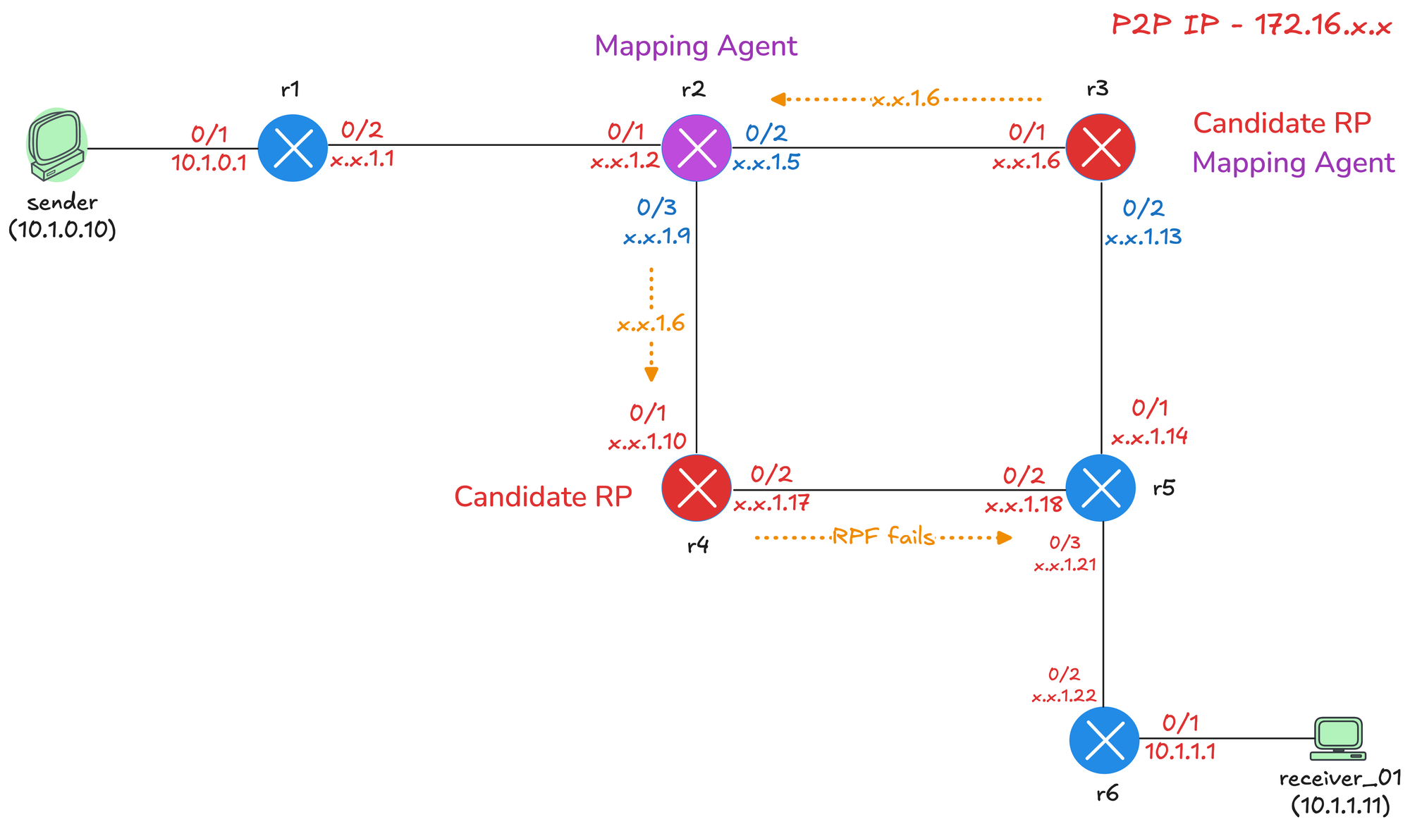
We will use a slightly modified diagram from the previous post, and here, we will make both r3 and r4 Candidate RPs, and we will also make r3 the Mapping Agent, just to show you that one router can serve both roles and also make r2 the Mapping Agent.
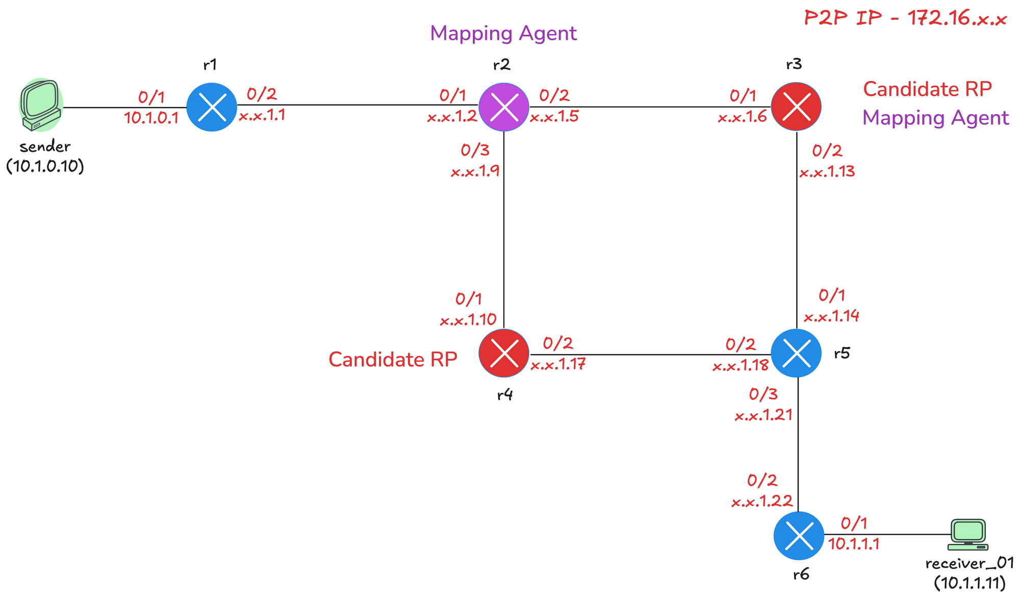
- r3 - Candidate RP and Mapping Agent
- r4 - Candidate RP
- r2 - Mapping Agent

Base Config
As usual, we will start with our base configuration. This includes enabling ip multicast-routing globally, enabling pim sparse-mode on all interfaces, and enabling ip pim autorp listener, which we will cover in a moment. I have also enabled OSPF throughout the network for unicast routing. Here is the configuration from r3 before we move forward.
Each router also has a loopback interface with IP address 10.0.0.x, where x is the router number. For example, r3 has 10.0.0.3, r4 has 10.0.0.4, and so on. Here is the configuration from r3 before we move forward.
ip multicast-routing
ip pim autorp listener
!
interface Loopback0
 ip address 10.0.0.3 255.255.255.255
 ip pim sparse-mode
 ip ospf 1 area 0.0.0.0
!
interface Ethernet0/1
 description r3 -> r2
 ip address 172.16.1.6 255.255.255.252
 ip pim sparse-mode
 ip ospf network point-to-point
 ip ospf 1 area 0.0.0.0
!
interface Ethernet0/2
 description r3 -> r5
 ip address 172.16.1.13 255.255.255.252
 ip pim sparse-mode
 ip ospf network point-to-point
 ip ospf 1 area 0.0.0.0
!
router ospf 1
 router-id 10.0.0.3
!If you remember from our previous posts, we disabled ip pim autorp to keep the debug outputs clean. We will not do that here since we are actually using Auto-RP. Auto-RP is enabled on all Cisco routers by default, so they are automatically members of 224.0.1.40 and listening for RP Discovery messages from the Mapping Agent.
For example, if I login to r3 now, I can see it's a member of 224.0.1.40 and listening for any advertisements coming from the mapping agent.
r3#show ip mroute
IP Multicast Routing Table
Flags: D - Dense, S - Sparse, B - Bidir Group, s - SSM Group, C - Connected,
       L - Local, P - Pruned, R - RP-bit set, F - Register flag,
       T - SPT-bit set, J - Join SPT, M - MSDP created entry, E - Extranet,
       X - Proxy Join Timer Running, A - Candidate for MSDP Advertisement,
       U - URD, I - Received Source Specific Host Report,
       Z - Multicast Tunnel, z - MDT-data group sender,
       Y - Joined MDT-data group, y - Sending to MDT-data group,
       G - Received BGP C-Mroute, g - Sent BGP C-Mroute,
       N - Received BGP Shared-Tree Prune, n - BGP C-Mroute suppressed,
       Q - Received BGP S-A Route, q - Sent BGP S-A Route,
       V - RD & Vector, v - Vector, p - PIM Joins on route,
       x - VxLAN group, c - PFP-SA cache created entry,
       * - determined by Assert, # - iif-starg configured on rpf intf,
       e - encap-helper tunnel flag, l - LISP decap ref count contributor
Outgoing interface flags: H - Hardware switched, A - Assert winner, p - PIM Join
                          t - LISP transit group
 Timers: Uptime/Expires
 Interface state: Interface, Next-Hop or VCD, State/Mode

(*, 224.0.1.40), 00:05:31/00:02:35, RP 0.0.0.0, flags: DCL
  Incoming interface: Null, RPF nbr 0.0.0.0
  Outgoing interface list:
    Ethernet0/2, Forward/Sparse, 00:05:27/stopped, flags:
    Ethernet0/1, Forward/Sparse, 00:05:31/stopped, flags:
Now, what is interesting is that we see the flag DCL for this group, and D stands for Dense. But hold on a second, are we not using Sparse Mode? Well, because of the chicken-and-egg problem we mentioned earlier, we need to use dense mode for the Auto-RP groups.
If I check who the RP is on r3, it shows nothing because we have not configured anything yet. The RP mapping table is empty, which is expected at this point. So, all good, let's move on and configure our Candidate RPs and Mapping Agents.
r3#show ip pim rp mapping
PIM Group-to-RP Mappings
AutoRP Listener
When you enable ip pim autorp listener, dense mode is enabled specifically for 224.0.1.39 and 224.0.1.40 only. All other multicast groups will use sparse mode as normal. This solves the chicken-and-egg problem because the Auto-RP messages can be flooded throughout the network using dense mode, allowing routers to learn the RP address. Once they know the RP, they can use sparse mode for all other multicast traffic.
The autorp listener command is the recommended solution because it enforces sparse mode for all groups except the two Auto-RP groups. Without it, you would have to use sparse-dense mode on your interfaces, which is risky because if the RP fails, all groups would fall back to dense mode and flood the entire network.
Candidate RP Configuration
To configure a router as a Candidate RP, we use the ip pim send-rp-announce command. The scope parameter sets the TTL of the RP Announce packet, which controls how many hops the announcement will travel. We set it to 10 here because we only have a handful of routers in our lab. In a larger network, you would set this higher to ensure the announcement reaches all parts of the network.
r3(config)#ip pim send-rp-announce loopback0 scope ?
<1-255> TTL of the RP announce packet
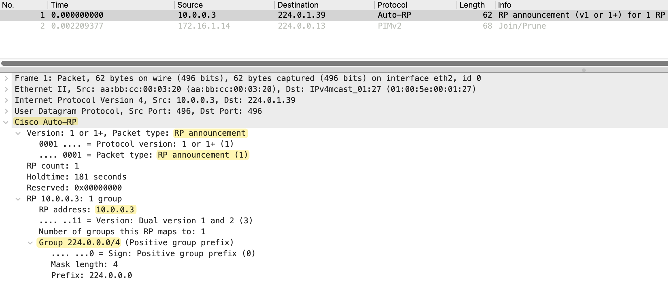
r3(config)#ip pim send-rp-announce loopback0 scope 10As soon as we enable this command, r3 starts sending RP Announce messages to 224.0.1.39 every 60 seconds. Looking at the packet capture, we can see the source is 10.0.0.3 (r3's loopback) and the destination is 224.0.1.39. The packet type is RP announcement, and it includes the RP address 10.0.0.3, a holdtime and the group range 224.0.0.0/4, which covers all multicast groups.
If we check the RP mapping on r3, it shows "This system is an RP (Auto-RP)". But do not be fooled by this. r3 just thinks it is an RP because it is announcing itself. At this point, no Mapping Agent has received this announcement and distributed it to the rest of the network. So r3 is not really the RP yet, it is just a Candidate RP advertising itself.
r3#show ip pim rp mapping
PIM Group-to-RP Mappings
This system is an RP (Auto-RP)
Looking at the multicast routing table on r3 again, we only had an entry for 224.0.1.40 before, but now we also have entries for 224.0.1.39. This is because r3 is now sending RP Announce messages to 224.0.1.39.
r3#show ip mroute
IP Multicast Routing Table
Flags: D - Dense, S - Sparse, B - Bidir Group, s - SSM Group, C - Connected,
       L - Local, P - Pruned, R - RP-bit set, F - Register flag,
       T - SPT-bit set, J - Join SPT, M - MSDP created entry, E - Extranet,
       X - Proxy Join Timer Running, A - Candidate for MSDP Advertisement,
       U - URD, I - Received Source Specific Host Report,
       Z - Multicast Tunnel, z - MDT-data group sender,
       Y - Joined MDT-data group, y - Sending to MDT-data group,
       G - Received BGP C-Mroute, g - Sent BGP C-Mroute,
       N - Received BGP Shared-Tree Prune, n - BGP C-Mroute suppressed,
       Q - Received BGP S-A Route, q - Sent BGP S-A Route,
       V - RD & Vector, v - Vector, p - PIM Joins on route,
       x - VxLAN group, c - PFP-SA cache created entry,
       * - determined by Assert, # - iif-starg configured on rpf intf,
       e - encap-helper tunnel flag, l - LISP decap ref count contributor
Outgoing interface flags: H - Hardware switched, A - Assert winner, p - PIM Join
                          t - LISP transit group
 Timers: Uptime/Expires
 Interface state: Interface, Next-Hop or VCD, State/Mode

(*, 224.0.1.39), 00:01:47/stopped, RP 0.0.0.0, flags: D
  Incoming interface: Null, RPF nbr 0.0.0.0
  Outgoing interface list:
    Ethernet0/2, Forward/Sparse, 00:01:47/stopped, flags:
    Ethernet0/1, Forward/Sparse, 00:01:47/stopped, flags:

(10.0.0.3, 224.0.1.39), 00:01:47/00:02:12, flags: PT
  Incoming interface: Loopback0, RPF nbr 0.0.0.0
  Outgoing interface list:
    Ethernet0/1, Prune/Sparse, 00:01:47/00:01:12, flags:
    Ethernet0/2, Prune/Sparse, 00:01:47/00:01:12, flags:

(*, 224.0.1.40), 00:55:07/00:02:52, RP 0.0.0.0, flags: DCL
  Incoming interface: Null, RPF nbr 0.0.0.0
  Outgoing interface list:
    Ethernet0/2, Forward/Sparse, 00:55:04/stopped, flags:
    Ethernet0/1, Forward/Sparse, 00:55:07/stopped, flags:
We can see a (*,G) entry for 224.0.1.39 with the D flag indicating dense mode. We also have an (S,G) entry for 10.0.0.3 to 224.0.1.39. The source 10.0.0.3 is r3's loopback, which confirms r3 is the one sending these announcements. The incoming interface is Loopback0, which is where the traffic originates. The outgoing interfaces are in Prune state because no Mapping Agent has joined this group yet to receive the announcements.
Looking at the debug output on r3, we can see both r2 and r5 have pruned themselves from this group. r2 (172.16.1.5) sent a Prune on Ethernet0/1 and r5 (172.16.1.14) sent a Prune on Ethernet0/2. This is expected because there is no Mapping Agent configured yet to receive these RP Announce messages. The announcements are being flooded using dense mode, but since no one is interested in receiving them, the downstream routers prune themselves.
previous iif and rpf_nbr is same as new one, ignoring it
PIM(0)[default]: Received v2 Join/Prune on Ethernet0/2 from 172.16.1.14, to us
PIM(0)[default]: Prune-list: (10.0.0.3/32, 224.0.1.39)
PIM(0)[default]: Prune Ethernet0/2/224.0.1.39 from (10.0.0.3/32, 224.0.1.39)
PIM(0)[default]: Received v2 Join/Prune on Ethernet0/1 from 172.16.1.5, to us
PIM(0)[default]: Prune-list: (10.0.0.3/32, 224.0.1.39)
PIM(0)[default]: Prune Ethernet0/1/224.0.1.39 from (10.0.0.3/32, 224.0.1.39)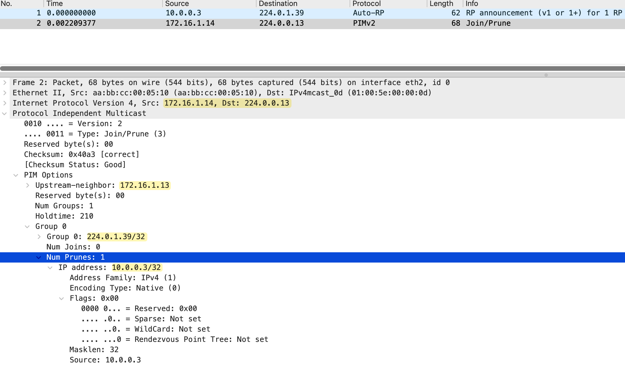
Mapping Agent Configuration
Now let's configure the Mapping Agent. We will make r2 the Mapping Agent using the ip pim send-rp-discovery command. Just like the Candidate RP configuration, we set the scope (TTL) to 10 to control how far the RP Discovery messages travel.
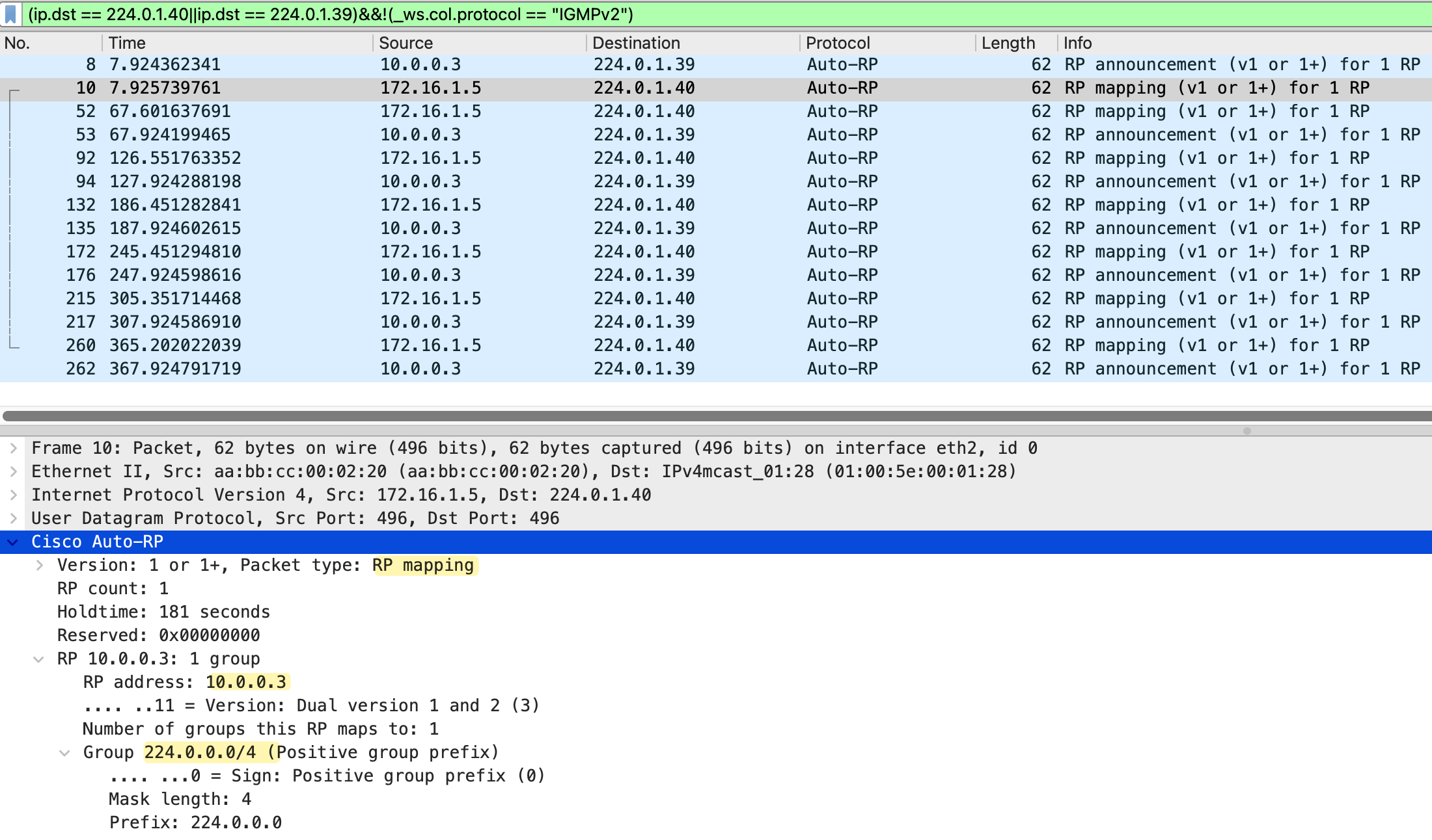
r2(config)#ip pim send-rp-discovery scope 10As soon as we enable this, r2 starts listening for RP Announce messages on 224.0.1.39 from Candidate RPs. When it receives an announcement from r3, it selects r3 as the RP and starts sending RP Discovery messages to 224.0.1.40 every 60 seconds, just like the Candidate RP sends its announcements every 60 seconds.
Looking at the packet capture, we can see both message types. The RP announcement messages from 10.0.0.3 (r3) going to 224.0.1.39, and the RP mapping messages from 172.16.1.5 (r2) going to 224.0.1.40. The RP mapping packet shows the packet type as "RP mapping", with the RP address 10.0.0.3 and the group range 224.0.0.0/4.
On r2, we can verify the Mapping Agent is working with show ip pim rp mapping command. The output shows "This system is an RP-mapping agent" and displays the elected RP as 10.0.0.3 (r3) for all multicast groups (224.0.0.0/4). The info source shows 10.0.0.3, which is where r2 learned about this Candidate RP.
r2#show ip pim rp mapping
PIM Group-to-RP Mappings
This system is an RP-mapping agent

Group(s) 224.0.0.0/4
  RP 10.0.0.3 (r3), v2v1
    Info source: 10.0.0.3 (r3), elected via Auto-RP
         Uptime: 00:05:38, expires: 00:02:22
On r3, the same command now shows the info source as 172.16.1.5 (r2), which is the Mapping Agent. This confirms that r3 is learning about itself being the RP through the Mapping Agent's RP Discovery messages, not just from its own announcement.
r3#show ip pim rp mapping
PIM Group-to-RP Mappings
This system is an RP (Auto-RP)

Group(s) 224.0.0.0/4
  RP 10.0.0.3 (?), v2v1
    Info source: 172.16.1.5 (r2), elected via Auto-RP
         Uptime: 00:05:53, expires: 00:02:02
Quick Verification
Let's quickly do a verification before proceeding. We can check the RP mapping on r6, which is further down in the network and not directly connected to either the Candidate RP or the Mapping Agent. The output shows r6 has learned that 10.0.0.3 (r3) is the RP for all multicast groups, and the info source is 172.16.1.5 (r2), the Mapping Agent. This confirms the RP Discovery messages are being flooded throughout the network.
r6#show ip pim rp mapping
PIM Group-to-RP Mappings

Group(s) 224.0.0.0/4
  RP 10.0.0.3 (r3), v2v1
    Info source: 172.16.1.5 (r2), elected via Auto-RP
         Uptime: 00:44:31, expires: 00:02:06
Now, let's send some multicast traffic from the sender and make receiver_01 join the group to make sure everything is working as expected.
receiver_01(config)#interface et0/1
receiver_01(config-if)#ip igmp join-group 239.1.1.1
sender#ping 239.1.1.1 repeat 100
Type escape sequence to abort.
Sending 100, 100-byte ICMP Echos to 239.1.1.1, timeout is 2 seconds:
Reply to request 0 from receiver_01 (10.1.1.11), 3 ms
Reply to request 1 from receiver_01 (10.1.1.11), 3 ms
Reply to request 2 from receiver_01 (10.1.1.11), 3 ms
Reply to request 3 from receiver_01 (10.1.1.11), 2 msr6#show ip mroute 239.1.1.1
IP Multicast Routing Table
Flags: D Dense, S - Sparse, B - Bidir Group, s - SSM Group, C - Connected,
L - Local, P - Pruned, R - RP-bit set, F - Register flag,
T - SPT-bit set, J - Join SPT, M - MSDP created entry, E - Extranet,
X - Proxy Join Timer Running, A - Candidate for MSDP Advertisement,
U - URD, I - Received Source Specific Host Report,
Z - Multicast Tunnel, z - MDT-data group sender,
Y - Joined MDT-data group, y - Sending to MDT-data group,
G - Received BGP C-Mroute, g - Sent BGP C-Mroute,
N - Received BGP Shared-Tree Prune, n - BGP C-Mroute suppressed,
Q - Received BGP S-A Route, q - Sent BGP S-A Route,
V - RD & Vector, v - Vector, p - PIM Joins on route,
x - VxLAN group, c - PFP-SA cache created entry,
* - determined by Assert, # - iif-starg configured on rpf intf,
e - encap-helper tunnel flag, l - LISP decap ref count contributor
Outgoing interface flags: H - Hardware switched, A - Assert winner, p - PIM Join
t - LISP transit group
Timers: Uptime/Expires
Interface state: Interface, Next-Hop or VCD, State/Mode
(*, 239.1.1.1), 00:00:17/stopped, RP 10.0.0.3, flags: SJC
Incoming interface: Ethernet0/2, RPF nbr 172.16.1.21
Outgoing interface list:
Ethernet0/1, Forward/Sparse, 00:00:17/00:02:41, flags:
(10.1.0.10, 239.1.1.1), 00:00:16/00:02:43, flags: JT
Incoming interface: Ethernet0/2, RPF nbr 172.16.1.21
Outgoing interface list:
Ethernet0/1, Forward/Sparse, 00:00:16/00:02:43, flags: Yep, everything looks good, and we can see the entry on r6's multicast routing table.
Further Changes
Now let's configure the other two routers as per the diagram. We make r4 a Candidate RP and r3 a Mapping Agent.
r4(config)#ip pim send-rp-announce loopback0 scope 10r3(config)#ip pim send-rp-discovery scope 10Once we make r4 a Candidate RP, it will win the election because it has the higher IP address on its loopback (10.0.0.4 compared to r3's 10.0.0.3). On both Mapping Agents (r2 and r3), we can see both Candidate RPs, but only one is elected.
r2#show ip pim rp mapping
PIM Group-to-RP Mappings
This system is an RP-mapping agent

Group(s) 224.0.0.0/4
  RP 10.0.0.4 (r4), v2v1
    Info source: 10.0.0.4 (r4), elected via Auto-RP
         Uptime: 00:04:15, expires: 00:02:43
  RP 10.0.0.3 (r3), v2v1
    Info source: 10.0.0.3 (r3), via Auto-RP
         Uptime: 00:57:46, expires: 00:02:12
r3#show ip pim rp mapping
PIM Group-to-RP Mappings
This system is an RP (Auto-RP)
This system is an RP-mapping agent
Group(s) 224.0.0.0/4
RP 10.0.0.4 (r4), v2v1
Info source: 10.0.0.4 (r4), elected via Auto-RP
Uptime: 00:02:14, expires: 00:02:42
RP 10.0.0.3 (?), v2v1
Info source: 10.0.0.3 (?), via Auto-RP
Uptime: 00:55:45, expires: 00:02:13On r2, the output shows both Candidate RPs. r4 (10.0.0.4) is marked as "elected via Auto-RP". The same applies on r3, which now shows "This system is an RP" and "This system is an RP-mapping agent", confirming it is serving both roles. However, r4 is still the elected RP because of the higher IP address.
On every other router, we only see the elected RP because the Mapping Agent only advertises the winner in its RP Discovery messages. For example, on r6, the output shows only r4 (10.0.0.4) as the RP, with the info source showing 172.16.1.13 (r3), which is one of the Mapping Agents.
r6#show ip pim rp mapping
PIM Group-to-RP Mappings

Group(s) 224.0.0.0/4
  RP 10.0.0.4 (r4), v2v1
    Info source: 172.16.1.13 (r3), elected via Auto-RP
         Uptime: 00:10:50, expires: 00:02:25
What is interesting is that I took a packet capture on r6 facing r5, and we can see RP mapping messages arriving from both Mapping Agents (172.16.1.9/172.16.1.5 from r2 and 172.16.1.13 from r3). Both are advertising the same elected RP (10.0.0.4).
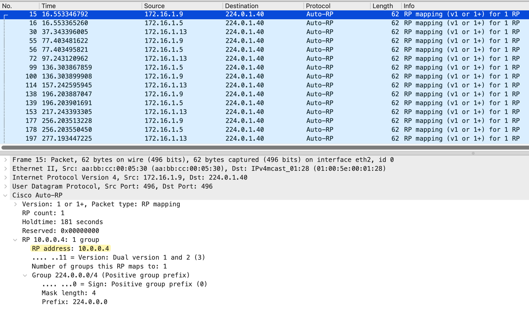
Looking at the packet capture and mroue output on r6, we see RP mapping messages from three source IPs - 172.16.1.5, 172.16.1.9, and 172.16.1.13. The first two belong to r2 (its interfaces toward r3 and r4), and the last one belongs to r3. Both are Mapping Agents sending RP Discovery messages.
r6#show ip mroute  224.0.1.40
IP Multicast Routing Table

(*, 224.0.1.40), 06:09:02/stopped, RP 0.0.0.0, flags: DCL
  Incoming interface: Null, RPF nbr 0.0.0.0
  Outgoing interface list:
    Ethernet0/2, Forward/Sparse, 06:09:02/stopped, flags:
    Ethernet0/1, Forward/Sparse, 06:09:02/stopped, flags:

(172.16.1.13, 224.0.1.40), 02:32:06/00:02:51, flags: LT
  Incoming interface: Ethernet0/2, RPF nbr 172.16.1.21
  Outgoing interface list:
    Ethernet0/1, Forward/Sparse, 02:32:06/stopped, flags:

(172.16.1.9, 224.0.1.40), 03:25:55/00:02:30, flags: LT
  Incoming interface: Ethernet0/2, RPF nbr 172.16.1.21
  Outgoing interface list:
    Ethernet0/1, Forward/Sparse, 03:25:55/stopped, flags:

(172.16.1.5, 224.0.1.40), 03:25:55/00:02:30, flags: LT
  Incoming interface: Ethernet0/2, RPF nbr 172.16.1.21
  Outgoing interface list:
Ethernet0/1, Forward/Sparse, 03:25:55/stopped, flags: 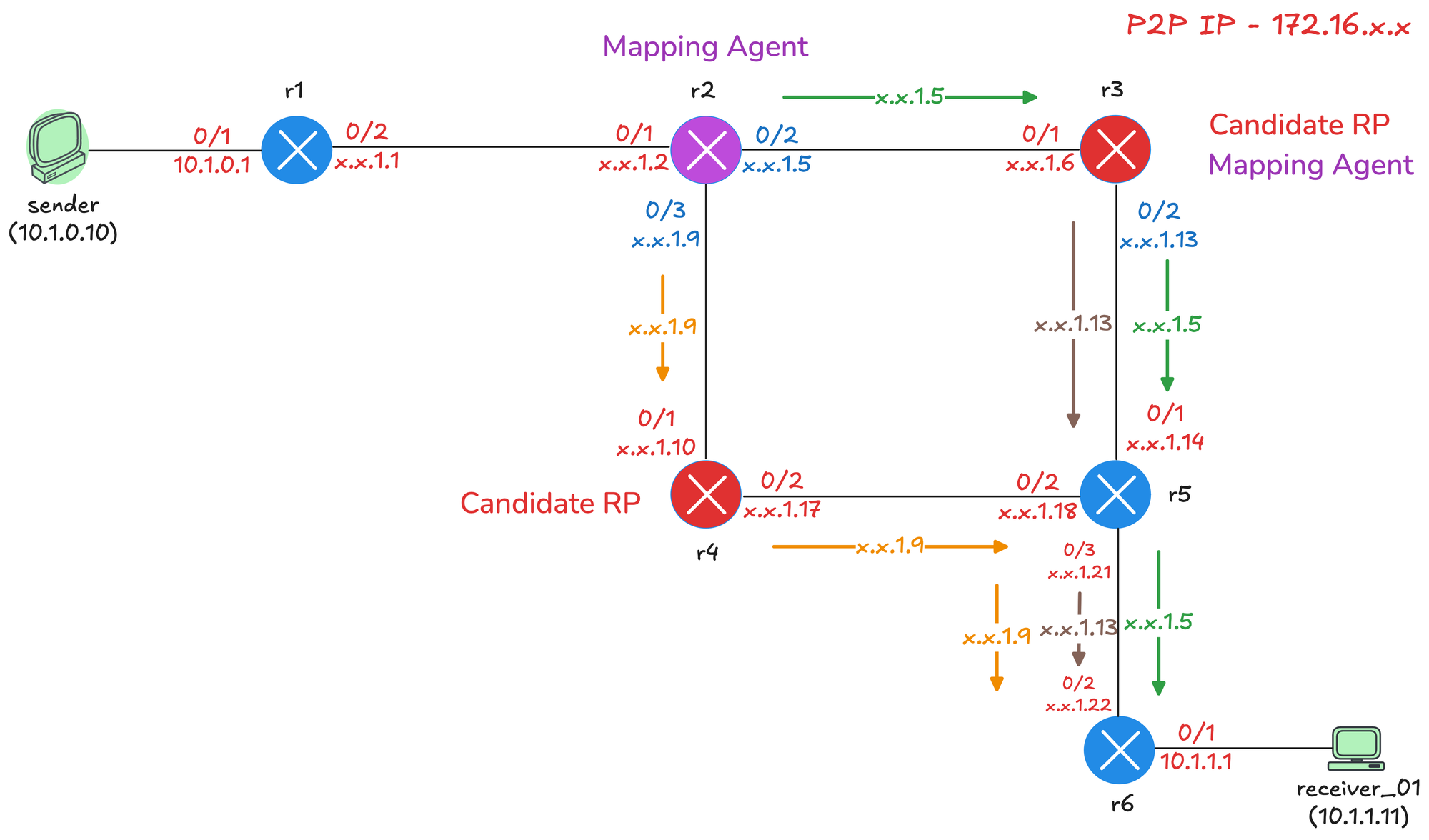
The diagram above shows how these messages traverse the network. When a Mapping Agent sends an RP Discovery message, it sends it out of all PIM-enabled interfaces because these messages use dense mode flooding.
- r2 sends messages out of both Ethernet0/2 (toward r3) and Ethernet0/3 (toward r4).
- r3 sends messages out of Ethernet0/2 (toward r5) and Ethernet0/1 (toward r2).
From r5's perspective, it receives RP mapping messages from multiple paths. Looking at the RPF information on r5, we can see that for 172.16.1.5 (r2's interface toward r3), the RPF interface is Ethernet0/1 with RPF neighbor r3. For 172.16.1.9 (r2's interface toward r4), the RPF interface is Ethernet0/2 with RPF neighbor r4. This confirms that r5 is receiving the messages on the correct RPF interfaces, so the traffic is accepted and forwarded downstream to r6.
r5#show ip rpf 172.16.1.5
RPF information for r2 (172.16.1.5)
  RPF interface: Ethernet0/1
  RPF neighbor: r3 (172.16.1.13)
  RPF route/mask: 172.16.1.4/30
  RPF type: unicast (ospf 1)
  Doing distance-preferred lookups across tables
  RPF topology: ipv4 multicast base, originated from ipv4 unicast base
r5#show ip rpf 172.16.1.9
RPF information for r2 (172.16.1.9)
RPF interface: Ethernet0/2
RPF neighbor: r4 (172.16.1.17)
RPF route/mask: 172.16.1.8/30
RPF type: unicast (ospf 1)
Doing distance-preferred lookups across tables
RPF topology: ipv4 multicast base, originated from ipv4 unicast baseThis is how dense mode flooding works for Auto-RP. The messages are flooded out of all interfaces and travel through the network, with each router performing RPF checks to ensure loop-free forwarding.
The message r3 sends out of Ethernet0/1 interface with the IP 172.16.1.6 won't make it to r6 because, on r5, the RPF check would have failed. From r5's perspective, the RPF neighbour to reach that IP is out of Ethernet0/1 rowards r3.
r5#show ip rpf 172.16.1.6
RPF information for r3 (172.16.1.6)
  RPF interface: Ethernet0/1
  RPF neighbor: r3 (172.16.1.13)
  RPF route/mask: 172.16.1.4/30
  RPF type: unicast (ospf 1)
  Doing distance-preferred lookups across tables
  RPF topology: ipv4 multicast base, originated from ipv4 unicast base
Removing AutoRP Listener on r5
Let's see what happens if we remove ip pim autorp listener on r5. Without AutoRP Listener, r5 will be running pure sparse mode on all interfaces. The Auto-RP messages to 224.0.1.39 and 224.0.1.40 will not be flooded using dense mode.
r5(config)#no ip pim autorp listenerr5#show ip pim rp mapping
PIM Group-to-RP Mappings
Group(s) 224.0.0.0/4
RP 10.0.0.4 (r4), v2v1
Info source: 172.16.1.13 (r3), elected via Auto-RP
Uptime: 00:02:56, expires: 00:02:04r5 will still learn the RP address because it is directly connected to r3, which is a Mapping Agent. The RP Discovery messages from r3 will reach r5 on the local segment. However, r5 will not flood these messages further downstream because it is running sparse mode. The problem is r6. Without the AutoRP Listener, r6 will not receive the RP Discovery messages from the Mapping Agents.
r6#show ip pim rp mapping
PIM Group-to-RP Mappings
Multicast PIM Sparse-Dense Mode
Let's look at another method to solve the chicken and egg problem. Instead of using AutoRP Listener, you can configure your interfaces to run in sparse-dense mode.
With sparse-dense mode, the router automatically decides which mode to use for each multicast group. If the router knows the RP for a group, it uses sparse mode. If it does not know the RP, it falls back to dense mode. This means the Auto-RP groups 224.0.1.39 and 224.0.1.40 will use dense mode because there is no RP configured for them, while all other groups will use sparse mode once the RP is learned.
To configure this, you simply replace ip pim sparse-mode with ip pim sparse-dense-mode on your interfaces. (And remove ip pim autorp listener of course)
interface Ethernet0/1
 description r3 -> r2
 ip address 172.16.1.6 255.255.255.252
 ip pim sparse-dense-mode
 ip ospf network point-to-point
 ip ospf 1 area 0.0.0.0
!
However, this is not the recommended approach. The danger is that if the RP fails or becomes unreachable for any reason, all multicast groups will fall back to dense mode and flood the entire network. With autorp listener, only the two Auto-RP groups use dense mode, and if the RP fails, other multicast traffic simply stops working rather than flooding everywhere.
You can remove this risk by disabling the dense mode fallback behavior. By default, Cisco routers have ip pim dm-fallback enabled. If you configure no ip pim dm-fallback, the router will not fall back to dense mode when the RP is unavailable. But at that point, you might as well just use AutoRP Listener.
r6#show run all | incl fallback
ip pim dm-fallback
AutoRP ACL Matching
By default, when you configure a Candidate RP, it announces itself for all multicast groups (224.0.0.0/4). You can use an ACL to limit which groups a Candidate RP will serve. This allows you to distribute the RP load across multiple routers.
Let's make r3 the RP for 239.1.1.0/24 and r4 the RP for everything else. On r3, we create a standard ACL that permits only the 239.1.1.0/24 range and apply it to the announce command using the group-list parameter.
!on r3

ip access-list standard MULTICAST_239_1
 10 permit 239.1.1.0 0.0.0.255
!
ip pim send-rp-announce Loopback0 scope 10 group-list MULTICAST_239_1
On r6, we can verify the RP mapping. We now see two entries. r4 (10.0.0.4) is the RP for 224.0.0.0/4, which covers all multicast groups. r3 (10.0.0.3) is the RP for 239.1.1.0/24 specifically. When a receiver joins a group in the 239.1.1.0/24 range, it will use r3 as the RP. For all other groups, it will use r4.
r6#show ip pim rp mapping
PIM Group-to-RP Mappings

Group(s) 224.0.0.0/4
  RP 10.0.0.4 (r4), v2v1
    Info source: 172.16.1.9 (r2), elected via Auto-RP
         Uptime: 00:15:51, expires: 00:02:44
Group(s) 239.1.1.0/24
  RP 10.0.0.3 (r3), v2v1
    Info source: 172.16.1.9 (r2), elected via Auto-RP
         Uptime: 00:00:15, expires: 00:02:41
Closing Up
That covers the fundamentals of Auto-RP. In the next post, we will look at Bootstrap Router (BSR), which is a standards-based alternative to Auto-RP. BSR solves the same problem of dynamic RP discovery, but works in a slightly different way and is not Cisco proprietary.