

In the previous posts, we covered the basics of multicast, including how sources send traffic to group addresses and how receivers use IGMP to signal their interest to the last hop router. We also looked at how IGMP snooping helps switches forward multicast traffic only to ports with interested receivers.
In this post, we will look at PIM, Protocol Independent Multicast. PIM is the protocol that routers use to build the multicast forwarding tree between the source and the receivers. There are different modes/flavours of PIM, and in this post, we will focus specifically on PIM Dense Mode.


PIM Overview
PIM, Protocol Independent Multicast, is the protocol routers use to build a loop-free multicast distribution tree from the source to the receivers. It is called protocol-independent because it does not rely on any specific unicast routing protocol. Instead, PIM uses whatever unicast routing table is already in place to make forwarding decisions. Whether you are running OSPF, EIGRP, BGP, or even static routes, PIM simply looks at the existing routing information to determine the best path back toward the source.
For multicast traffic to flow through the network, you need to enable PIM on all interfaces along the path from the source to the receivers. If an interface does not have PIM enabled, multicast traffic will not be forwarded out of that interface. This includes interfaces facing other routers as well as interfaces facing the source and receiver segments.
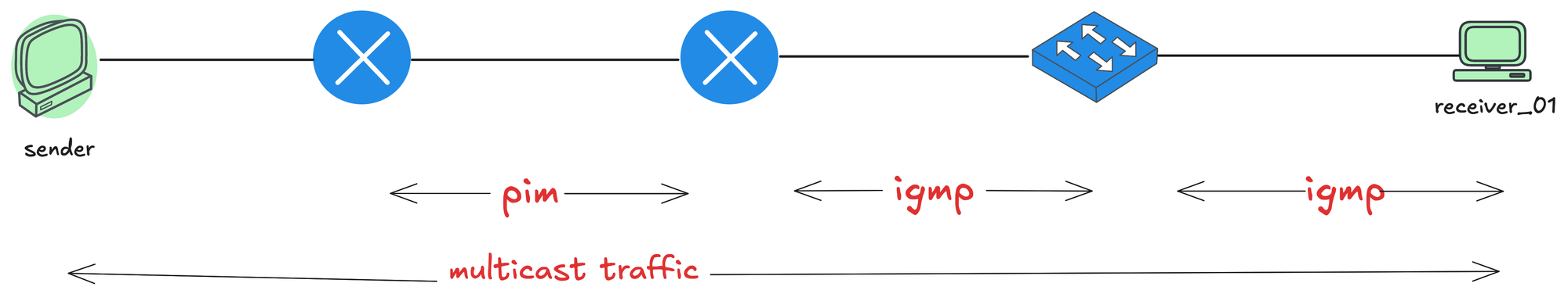
We already covered IGMP, which works on the local segment between receivers and the last hop router. IGMP allows receivers to signal their interest in a multicast group. PIM, on the other hand, works between routers. Once the last hop router learns about interested receivers through IGMP, PIM takes over and builds the multicast forwarding path across the network back toward the source.
Enabling PIM
Remember, in the previous post, we enabled IGMP by enabling PIM on the interfaces. When you enable PIM on an interface, the router starts sending PIM Hello messages out of that interface. These Hello messages are used to discover other PIM routers on the same segment and establish neighbour relationships.
PIM Hello messages are sent to the multicast address 224.0.0.13, which represents all PIM routers on the local segment. The source address is the IP address of the interface sending the Hello, and the TTL is set to 1, meaning the message never leaves the local segment.
PIM routers must establish neighbour relationships before they can exchange other PIM messages and build multicast routing entries. Hello messages are also used to maintain these neighbour relationships and negotiate protocol parameters between routers. If you have two routers facing each other, you can enable PIM on the interfaces with the following configuration.
ip multicast-routing
!
interface Ethernetx/x
 ip pim dense-mode
As soon as PIM is enabled, the routers start sending Hello messages to 224.0.0.13. In the packet capture below, you can see both routers (172.16.1.1 and 172.16.1.2) exchanging Hello messages.
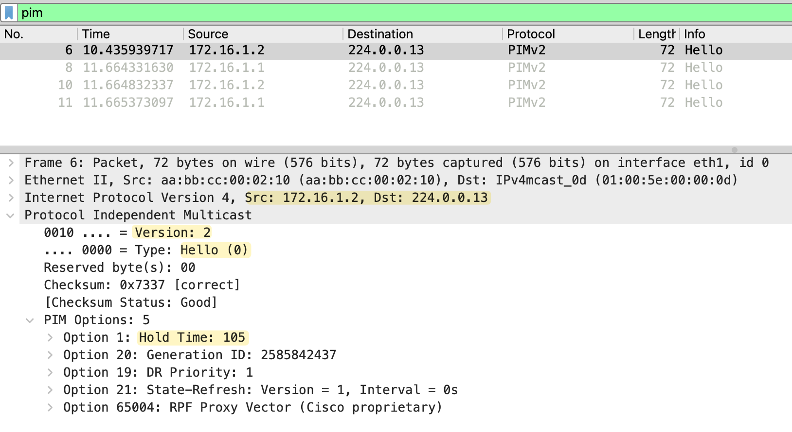
The PIM Hello message includes several options such as Hold Time and DR Priority. The Hold Time tells the neighbour how long to wait before considering the neighbour down if no further Hellos are received. By default, PIM Hellos are sent every 30 seconds with a Hold Time of 105 seconds (3.5 times the hello interval). You can verify PIM neighbors using the following commands.
r2#show ip pim interface

Address      Interface      Ver/   Nbr    Query  DR     DR
                            Mode   Count  Intvl  Prior
172.16.1.2   Ethernet0/1    v2/D   1      30     1      172.16.1.2
This output shows that PIM is enabled on Ethernet0/1 with address 172.16.1.2. The Ver/Mode column shows v2/D, which means PIM version 2 running in Dense Mode. The Nbr Count is 1, indicating there is one PIM neighbour on this interface. The Query Int shows the Hello interval, which is 30 seconds by default.
r2#show ip pim neighbor
PIM Neighbor Table
Mode: B - Bidir Capable, DR - Designated Router, N - Default DR Priority,
      P - Proxy Capable, S - State Refresh Capable, G - GenID Capable,
      L - DR Load-balancing Capable
Neighbor          Interface                Uptime/Expires    Ver   DR
Address                                                            Prio/Mode
172.16.1.1        Ethernet0/1              00:02:23/00:01:20 v2    1 / S P G
This output shows the neighbor 172.16.1.1 learned on Ethernet0/1. The Uptime/Expires field shows how long the neighbor has been up and when it will expire if no more Hellos are received. The neighbor is marked as DR, which stands for Designated Router. We will cover the Designated Router election later in this series.
PIM Dense Mode
PIM Dense Mode is not commonly used in production environments. It is mainly used for labbing and testing purposes. The reason is that Dense Mode uses a flood and prune approach. It assumes that every subnet in the network has interested receivers, so it floods multicast traffic everywhere first. Routers that do not have interested receivers then send prune messages to stop the traffic. This behaviour is inefficient and wastes bandwidth, especially in large networks where most subnets may not have any receivers at all.

When a source starts sending multicast traffic, the traffic is flooded out of all PIM-enabled interfaces throughout the network. Routers that do not have any interested receivers send prune messages back upstream to stop receiving the traffic.
Flood and Prune Mechanism
When a source starts sending multicast traffic, PIM Dense Mode floods the traffic out of all PIM-enabled interfaces throughout the network. Every router receives the multicast stream and forwards it to all its neighbors, regardless of whether there are interested receivers or not. This is the flood part of the flood and prune mechanism.
As the traffic flows through the network, routers build what is called a Shortest Path Tree (SPT). The SPT is a loop-free tree rooted at the source, with branches extending toward all parts of the network. The tree follows the shortest path based on the unicast routing table.
Once the flooding happens, routers that do not have any interested receivers on their downstream interfaces send Prune messages back upstream. A Prune message tells the upstream router to stop sending multicast traffic for that specific group down that particular interface. When the upstream router receives the Prune, it removes that interface from its outgoing interface list for the multicast group.
The pruned state does not last forever. By default, the prune times out after 3 minutes. In PIM version 1, when the prune timer expires, the traffic is flooded again and routers without receivers have to prune again. This cycle repeats, causing periodic flood and prune behavior. PIM version 2 improves this with a feature called State Refresh. Instead of waiting for the prune to expire and flooding again, routers (FHR) periodically send State Refresh messages through the network. Each time a router receives a State Refresh, the prune timer is reset to three minutes. This prevents the repeated flood and prune behavior seen in version 1 (more on state State Refresh later)
PIM Dense Lab
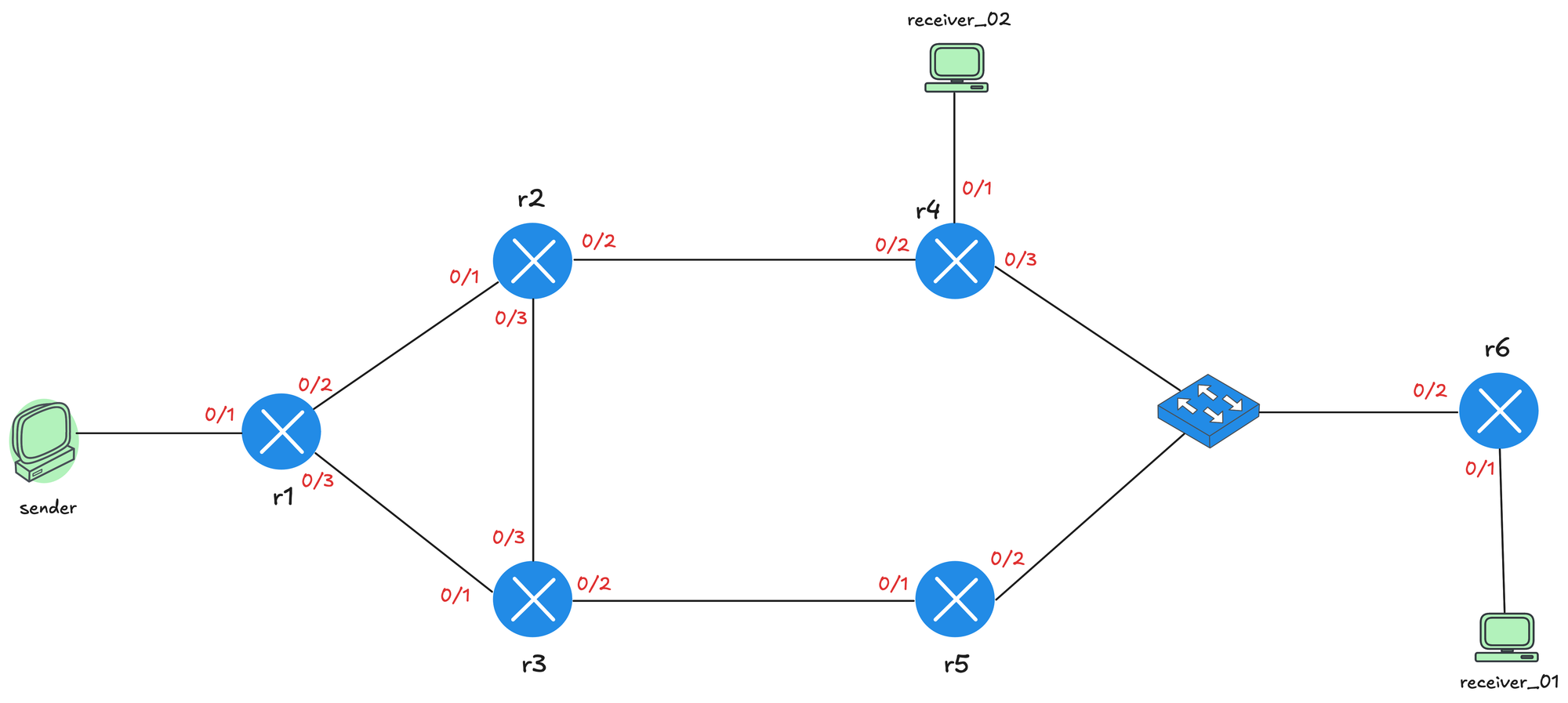
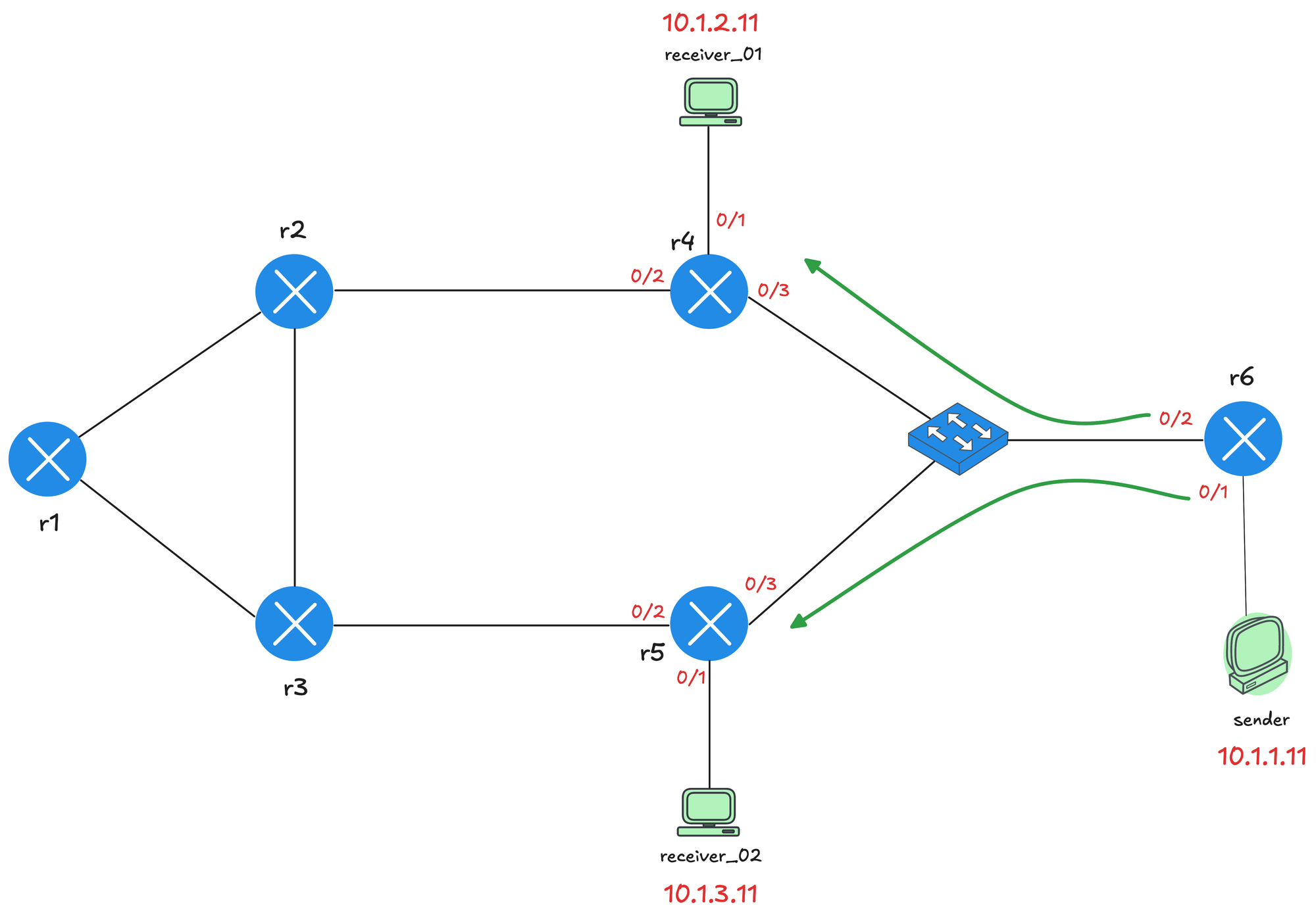
We will use the topology shown below for the lab. The sender is connected to r1, which acts as the first hop router (FHR). From r1, there are two paths through the network. The upper path goes through r2 and r4, while the lower path goes through r3 and r5. Both paths converge at a switch, which connects to r6. r6 is the last hop router, and receiver_01 is connected to it. There is also a second receiver, receiver_02, connected directly to r4.
I have configured OSPF on all the routers so we have full unicast reachability throughout the network. This means I can ping between the sender and receivers using their unicast IP addresses. Remember, PIM is protocol independent and relies on the unicast routing table to make forwarding decisions.
On all routers, multicast routing is enabled, and PIM is configured on the interfaces connecting routers, senders, and receivers. I have also disabled Auto RP for now since we do not need it for PIM Dense Mode. Here is the relevant config from r1 so, you will get an idea.
ip multicast-routing
no ip pim autorp
!
interface Ethernet0/1
 description r1 -> sender
 ip address 10.1.0.1 255.255.255.0
 ip pim dense-mode
 ip ospf network point-to-point
 ip ospf 1 area 0.0.0.0
!
interface Ethernet0/2
 description r1 -> r2
 ip address 172.16.1.1 255.255.255.252
 ip pim dense-mode
 ip ospf network point-to-point
 ip ospf 1 area 0.0.0.0
!
interface Ethernet0/3
 description r1 -> r3
 ip address 172.16.1.5 255.255.255.252
 ip pim dense-mode
 ip ospf network point-to-point
 ip ospf 1 area 0.0.0.0
!
router ospf 1
 router-id 10.0.0.1
 passive-interface Ethernet0/1
!
Here is also the PIM related output from r1. We should see two PIM neighbourships from r1 (to both r2 and r3)
r1#show ip pim interface

Address       Interface      Ver/   Nbr    Query  DR      DR
                             Mode   Count  Intvl  Prior
10.1.0.1      Ethernet0/1    v2/D   0      30     1       10.1.0.1
172.16.1.1    Ethernet0/2    v2/D   1      30     1       172.16.1.2
172.16.1.5    Ethernet0/3    v2/D   1      30     1       172.16.1.6
Please note here on r1, you also see an entry for Ethernet0/1 which connects to the source but under Nbr Count there is a 0 which means there is no PIM neighbour on that interface as we expected.
r1#show ip pim neighbor
PIM Neighbor Table
Mode: B - Bidir Capable, DR - Designated Router, N - Default DR Priority,
      P - Proxy Capable, S - State Refresh Capable, G - GenID Capable,
      L - DR Load-balancing Capable
Neighbor          Interface                Uptime/Expires    Ver   DR
Address                                                            Prio/Mode
172.16.1.2        Ethernet0/2              00:16:36/00:01:24 v2    1 / DR S P G
172.16.1.6        Ethernet0/3              00:16:32/00:01:26 v2    1 / DR S P G
Sending Multicast Traffic
Let's start by sending some multicast traffic from the sender. We are not going to join any group yet, just sending a few multicast packets into the network to see what exactly happens. From the sender, we send a ping to the multicast address 239.1.1.1.
sender#ping 239.1.1.1 repeat 3As soon as we do this, we can head over to r1 and look at the multicast routing table using the show ip mroute command. You will see two entries in the output. The first entry is (*, 239.1.1.1), which is called a star,G entry. We will ignore this for now because PM-Dense Mode doesn't use this entry for forwarding multicast packets.
r1#show ip mr
IP Multicast Routing Table
Flags: D - Dense, S - Sparse, B - Bidir Group, s - SSM Group, C - Connected,
       L - Local, P - Pruned, R - RP-bit set, F - Register flag,
       T - SPT-bit set, J - Join SPT, M - MSDP created entry, E - Extranet,
       X - Proxy Join Timer Running, A - Candidate for MSDP Advertisement,
       U - URD, I - Received Source Specific Host Report,
       Z - Multicast Tunnel, z - MDT-data group sender,
       Y - Joined MDT-data group, y - Sending to MDT-data group,
       G - Received BGP C-Mroute, g - Sent BGP C-Mroute,
       N - Received BGP Shared-Tree Prune, n - BGP C-Mroute suppressed,
       Q - Received BGP S-A Route, q - Sent BGP S-A Route,
       V - RD & Vector, v - Vector, p - PIM Joins on route,
       x - VxLAN group, c - PFP-SA cache created entry,
       * - determined by Assert, # - iif-starg configured on rpf intf,
       e - encap-helper tunnel flag, l - LISP decap ref count contributor
Outgoing interface flags: H - Hardware switched, A - Assert winner, p - PIM Join
                          t - LISP transit group
 Timers: Uptime/Expires
 Interface state: Interface, Next-Hop or VCD, State/Mode

(*, 239.1.1.1), 00:00:12/stopped, RP 0.0.0.0, flags: D
  Incoming interface: Null, RPF nbr 0.0.0.0
  Outgoing interface list:
    Ethernet0/3, Forward/Dense, 00:00:12/stopped, flags:
    Ethernet0/2, Forward/Dense, 00:00:12/stopped, flags:

(10.1.0.10, 239.1.1.1), 00:00:12/00:02:47, flags: PT
  Incoming interface: Ethernet0/1, RPF nbr 0.0.0.0
  Outgoing interface list:
    Ethernet0/2, Prune/Dense, 00:00:12/00:02:47, flags:
    Ethernet0/3, Prune/Dense, 00:00:10/00:02:49, flags:
The second entry is the S,G (Source, Group) entry, which shows the source IP address (10.1.0.10) and the multicast group address (239.1.1.1). The incoming interface is Ethernet0/1, which is the interface connected to the sender. The RPF neighbor is set to 0.0.0.0 because the source is directly connected to r1.
Prune
The outgoing interface list, also known as the OIL, shows Ethernet0/2 and Ethernet0/3. These are the interfaces connected to r2 and r3 respectively. Remember, in Dense Mode, the traffic is flooded out of all PIM-enabled interfaces. However, notice that both interfaces show Prune/Dense in the state. This means both r2 and r3 have sent Prune messages back to r1 saying they do not have any interested receivers and do not want the multicast traffic anymore.
r1#terminal monitor
r1#debug ip pim

previous iif and rpf_nbr is same as new one, ignoring it
PIM(0)[default]: Received v2 Join/Prune on Ethernet0/2 from 172.16.1.2, to us
PIM(0)[default]: Prune-list: (10.1.0.10/32, 239.1.1.1)
PIM(0)[default]: Prune Ethernet0/2/239.1.1.1 from (10.1.0.10/32, 239.1.1.1)
PIM(0)[default]: Received v2 Join/Prune on Ethernet0/3 from 172.16.1.6, to us
PIM(0)[default]: Prune-list: (10.1.0.10/32, 239.1.1.1)
PIM(0)[default]: Prune Ethernet0/3/239.1.1.1 from (10.1.0.10/32, 239.1.1.1)
As we can see in the packet capture below, this is a Prune message sent from r2 (172.16.1.2) to r1. PIM uses a single message type called Join/Prune for both join and prune operations, which is why you see Type: Join/Prune (3) in the capture.
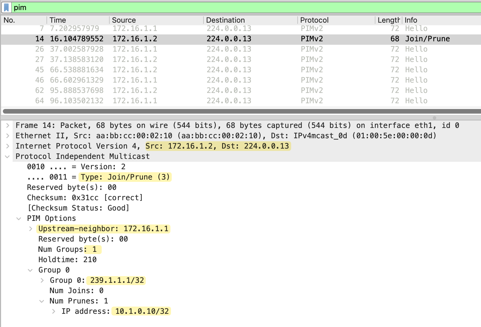
The message is sent to 224.0.0.13, the all PIM routers address, and includes the upstream neighbor field set to 172.16.1.1, which is r1. The Num Groups field shows 1, indicating this message applies to one multicast group. Looking at the group details, we can see Group 239.1.1.1, which is the multicast group address. The IP address 10.1.0.10/32 in the prune list identifies the source being pruned.
Please note that even when a router prunes a specific multicast group, it still keeps the state in the multicast routing table. The interfaces are marked as pruned, but the entry remains. This means if there are 100 multicast groups being sent across the network, every router has to maintain state for all 100 groups, even if it has no interested receivers for any of them.
This is another reason why PIM Dense Mode is not widely used in production networks. The router memory and processing overhead can grow quickly as the number of multicast groups increases. When we look at PIM Sparse Mode in the next post, you will see how it handles this differently.
RPF Checks
The diagram below shows the multicast traffic flow through the network. The green arrows represent the pathå where traffic flows successfully, and the red arrows show where traffic is rejected due to RPF check failures.
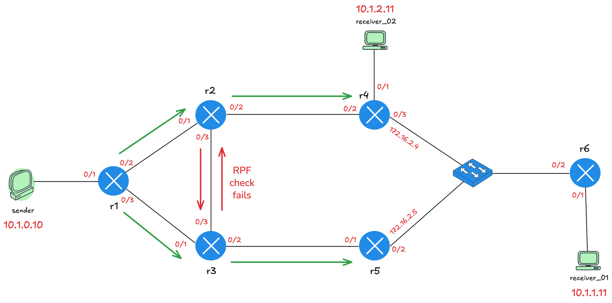
When multicast traffic arrives at a router, the router performs an RPF (Reverse Path Forwarding) check. The router looks at the source IP address of the multicast packet and checks which interface it would use to reach that source based on the unicast routing table. If the packet arrives on that interface, the RPF check passes, and the traffic is accepted. If the packet arrives on a different interface, the RPF check fails, and the traffic is dropped. This is how PIM prevents loops in the multicast network.
For example, from r2's perspective, to reach the source 10.1.0.10, the best path is via Ethernet0/1, which connects to r1. So when r2 receives multicast traffic from r3 on Ethernet0/3, the RPF check fails and the traffic is dropped. The same applies to r3 when it receives traffic from r2.
r2#show ip route 10.1.0.10
Routing entry for 10.1.0.0/24
  Known via "ospf 1", distance 110, metric 20, type intra area
  Last update from 172.16.1.1 on Ethernet0/1, 01:17:09 ago
  Routing Descriptor Blocks:
  * 172.16.1.1, from 10.0.0.1, 01:17:09 ago, via Ethernet0/1
      Route metric is 20, traffic share count is 1
PIM Assert
Between r4 and r5, there is an interesting situation. Both routers are connected to the same LAN segment via the switch.
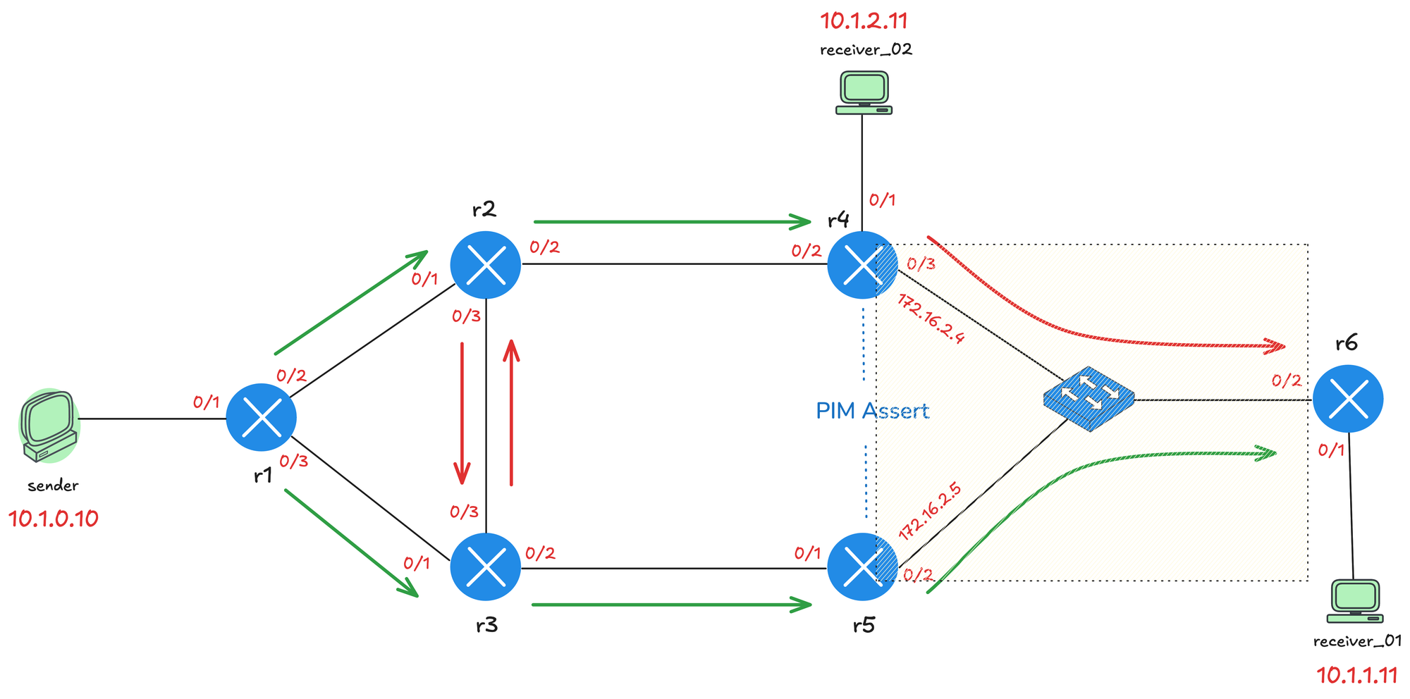
When multicast traffic is flooded, both r4 and r5 could be sending the same multicast traffic toward r6, and they will also receive each other's traffic on that shared segment. When this happens, it triggers a PIM Assert process to elect a single forwarder for that segment. The PIM Assert election works as follows.
- First, the router with the lowest administrative distance to the source wins. This only comes into play if you are using multiple routing protocols.
- If the administrative distance is equal, then the router with the best unicast routing metric toward the source wins.
- If both the administrative distance and metric are the same, the router with the highest IP address becomes the forwarder.
In this case, r5 wins the Assert election (by having a higher IP) and becomes the designated forwarder for the segment.
!r4

PIM(0)[default]: Received v2 Assert on Ethernet0/3 from 172.16.2.5
PIM(0)[default]: Assert metric to source 10.1.0.10 is [110/30]
PIM(0)[default]: We lose, our metric [110/30
!r5
PIM(0)[default]: Send v2 Assert on Ethernet0/2 for 239.1.1.1,
source 10.1.0.10, metric [110/30]
PIM(0)[default]: Assert metric to source 10.1.0.10 is [110/30]
PIM(0)[default]: We win, our metric [110/30]PIM State Refresh
PIM State Refresh is a feature in PIM version 2 that prevents the periodic flood and prune behavior seen in version 1. Without State Refresh, the prune state expires after 3 minutes, and the traffic is flooded again, requiring routers to send new prune messages. This cycle repeats and wastes bandwidth.
With State Refresh enabled, the first hop router periodically sends State Refresh messages down the multicast tree. When downstream routers receive a State Refresh message, they reset their prune timers back to 3 minutes. This keeps the pruned state active without needing to flood the traffic again.
PIM State Refresh is enabled by default on Cisco devices running PIM Dense Mode. All PIM routers automatically process and forward State Refresh messages without any configuration. You can check this by running the following command.
r2#show ip pim interface Ethernet0/1 detail
Ethernet0/1 is up, line protocol is up
  Internet address is 172.16.1.2/30
  Multicast switching: fast
  Multicast packets in/out: 1/0
  Multicast TTL threshold: 0
  PIM: enabled
    PIM version: 2, mode: dense
    PIM DR: 172.16.1.2 (this system)
    PIM neighbor count: 1
    PIM Hello/Query interval: 30 seconds
    PIM Hello packets in/out: 30/31
    PIM J/P interval: 60 seconds
    PIM State-Refresh processing: enabled
    PIM State-Refresh origination: disabled
    PIM NBMA mode: disabled
    PIM ATM multipoint signalling: disabled
    PIM domain border: disabled
    PIM neighbors rpf proxy capable: TRUE
    PIM BFD: disabled
    PIM Non-DR-Join: FALSE
  Multicast Tagswitching: disabled
However, the origination of State Refresh messages is disabled by default. To enable it, you need to configure the first hop router, specifically on the interface closest to the source. You can enable State Refresh origination using the ip pim state-refresh origination-interval command and specify the interval in seconds. For example, ip pim state-refresh origination-interval 30 would send State Refresh messages every 30 seconds.
!r1

interface Ethernet0/1
 description r1 -> sender
 ip address 10.1.0.1 255.255.255.0
 ip pim state-refresh origination-interval 30
 ip pim dense-mode
 ip ospf network point-to-point
 ip ospf 1 area 0.0.0.0
!
r1#terminal monitor
r1#debug ip pim
Originating refresh message for (10.1.0.10,239.1.1.1)
Send SR on Ethernet0/2 for (10.1.0.10,239.1.1.1) TTL=255
lags: prune-indicator
Send SR on Ethernet0/3 for (10.1.0.10,239.1.1.1) TTL=255
flags: prune-indicator r2#terminal monitor
r2#debug ip pim
Received v2 State-Refresh on Ethernet0/3 from 172.16.1.18
SR on oif from 172.16.1.18 orig 10.1.0.1 for (10.1.0.10,239.1.1.1)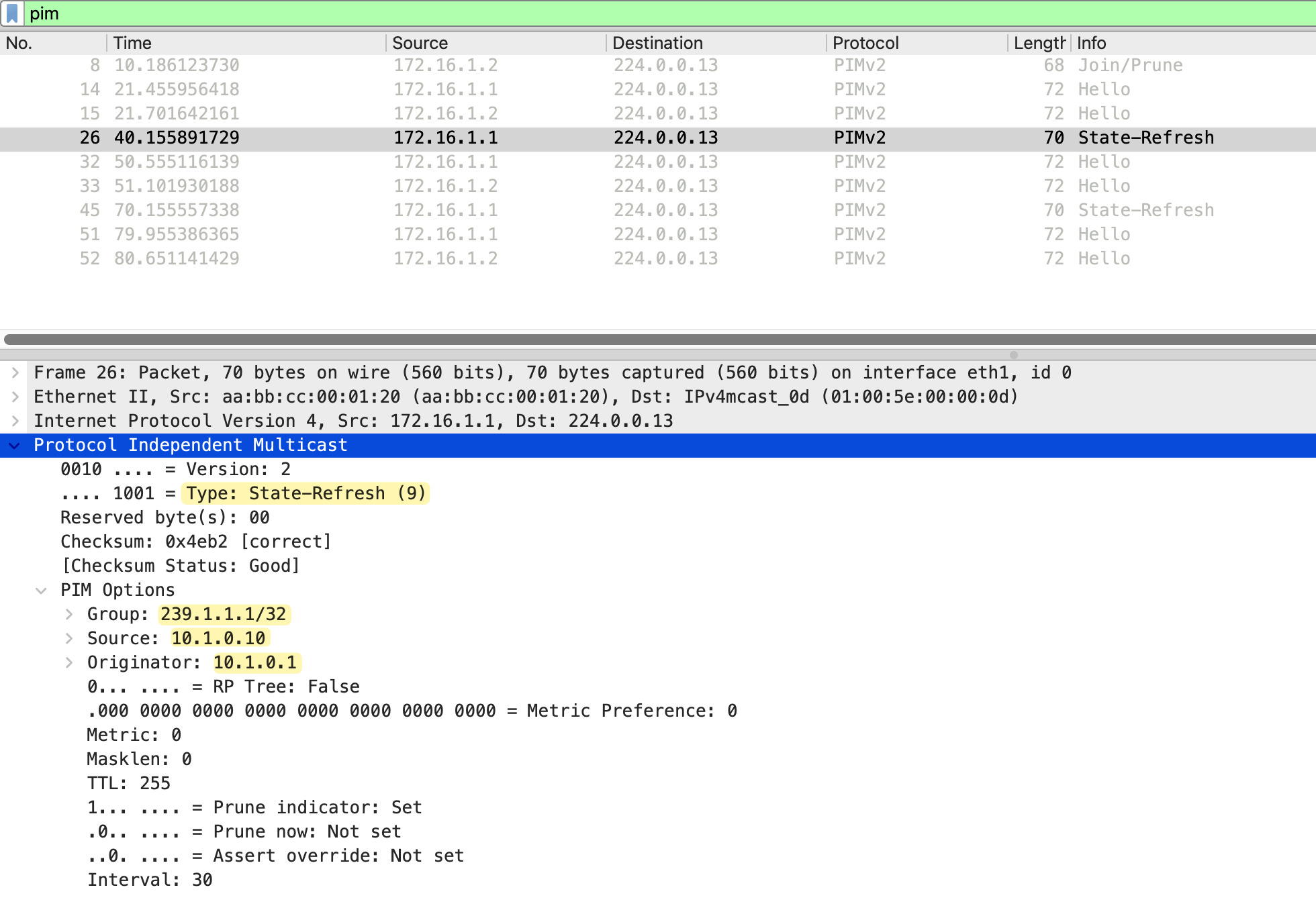
PIM Dense Mode with Receivers
Let's now add a receiver to the mix. First, I am going to make receiver_01 join the multicast group 239.1.1.1, but I am not going to send any multicast traffic from the sender yet, just to see what happens. I will also add the same diagram here so, you don't have to scroll all the way back 😄

#r6

interface Ethernet0/1
 ip igmp join-group 239.1.1.1
After configuring receiver_01 to join the group, we can check the multicast routing table on r6. At this point, we only see a star,G entry for 239.1.1.1. The incoming interface is Null, this is because r6 does not know anything about this multicast group yet. No source is sending traffic, so r6 has no information about where the traffic should come from. It only knows that there is an interested receiver on its local segment.
r6#show ip mroute | beg  Timers
 Timers: Uptime/Expires
 Interface state: Interface, Next-Hop or VCD, State/Mode

(*, 239.1.1.1), 00:02:18/00:02:39, RP 0.0.0.0, flags: DC
  Incoming interface: Null, RPF nbr 0.0.0.0
  Outgoing interface list:
    Ethernet0/2, Forward/Dense, 00:02:18/stopped, flags:
    Ethernet0/1, Forward/Dense, 00:02:18/stopped, flags:
Now let's start sending traffic from the sender.
sender#ping 239.1.1.1 repeat 100On r1, we can see the S,G entry for 10.1.0.10 and 239.1.1.1. The incoming interface is Ethernet0/1, which connects to the sender. Looking at the outgoing interface list, Ethernet0/2 toward r2 is in Prune state, which means r2 has sent a prune message saying it does not need this multicast traffic. Ethernet0/3 toward r3 is in Forward state, so traffic is flowing down that path.
r1#show ip mroute | beg Timers
 Timers: Uptime/Expires
 Interface state: Interface, Next-Hop or VCD, State/Mode

(*, 239.1.1.1), 00:00:08/stopped, RP 0.0.0.0, flags: D
  Incoming interface: Null, RPF nbr 0.0.0.0
  Outgoing interface list:
    Ethernet0/3, Forward/Dense, 00:00:08/stopped, flags:
    Ethernet0/2, Forward/Dense, 00:00:08/stopped, flags:

(10.1.0.10, 239.1.1.1), 00:00:08/00:02:51, flags: T
  Incoming interface: Ethernet0/1, RPF nbr 0.0.0.0
  Outgoing interface list:
    Ethernet0/2, Prune/Dense, 00:00:08/00:02:51, flags:
    Ethernet0/3, Forward/Dense, 00:00:08/stopped, flags:
On r3, the incoming interface is Ethernet0/1, which is r1. In the outgoing interface list, Ethernet0/3 toward r2 is in Prune state as expected. Ethernet0/2 toward r5 is in Forward state, so traffic continues down the lower path. Remember the PIM Assert we discussed earlier where r5 won the election. That is why the traffic is flowing via r1, r3, r5, and then to r6.
r3#show ip mroute | beg Timers
 Timers: Uptime/Expires
 Interface state: Interface, Next-Hop or VCD, State/Mode

(*, 239.1.1.1), 00:02:22/stopped, RP 0.0.0.0, flags: D
  Incoming interface: Null, RPF nbr 0.0.0.0
  Outgoing interface list:
    Ethernet0/3, Forward/Dense, 00:02:22/stopped, flags:
    Ethernet0/2, Forward/Dense, 00:02:22/stopped, flags:
    Ethernet0/1, Forward/Dense, 00:02:22/stopped, flags:

(10.1.0.10, 239.1.1.1), 00:02:22/00:00:37, flags: T
  Incoming interface: Ethernet0/1, RPF nbr 172.16.1.5
  Outgoing interface list:
    Ethernet0/2, Forward/Dense, 00:02:22/stopped, flags:
    Ethernet0/3, Prune/Dense, 00:02:22/00:02:37, flags: A
On r6, the incoming interface is Ethernet0/2, which is the switch on the LAN segment. The outgoing interface list shows Ethernet0/1 in Forward state, which is the interface connected to receiver_01. The multicast traffic is now flowing all the way from the sender through r1, r3, r5, and r6 to reach receiver_01.
r6#show ip mroute | beg  Timers
 Timers: Uptime/Expires
 Interface state: Interface, Next-Hop or VCD, State/Mode

(*, 239.1.1.1), 00:09:08/stopped, RP 0.0.0.0, flags: DC
  Incoming interface: Null, RPF nbr 0.0.0.0
  Outgoing interface list:
    Ethernet0/2, Forward/Dense, 00:09:08/stopped, flags:
    Ethernet0/1, Forward/Dense, 00:09:08/stopped, flags:

(10.1.0.10, 239.1.1.1), 00:03:40/00:02:49, flags: T
  Incoming interface: Ethernet0/2, RPF nbr 172.16.2.5
  Outgoing interface list:
    Ethernet0/1, Forward/Dense, 00:03:40/stopped, flags:
You can use show IP igmp groups command to verify that a receiver has actually joined the multicast group on the router (LHR). The Last Reporter column shows only one IGMP host, which indicates that it has sent either an unsolicited IGMP Join or IGMP Report in response to an IGMP Query from the PIM router for that particular group. You must only see one Last Reporter per Group Address.
r6#show ip igmp groups
IGMP Connected Group Membership
Group Address    Interface        Uptime    Expires   Last Reporter
239.1.1.1        Ethernet0/1      00:22:27  00:02:35  10.1.1.11
PIM Graft
When a pruned branch needs to start receiving multicast traffic again, PIM uses a Graft message. For example, if a new receiver joins a multicast group on a segment that was previously pruned, the Graft message allows the router to immediately request the multicast traffic from its upstream neighbor.
Unlike other PIM messages, the Graft message is sent as unicast directly to the upstream neighbor. When the upstream router receives the Graft, it adds the interface back to the outgoing interface list and resumes forwarding multicast traffic. The upstream router also sends a Graft Ack (acknowledgment) back to confirm that the graft was successful.
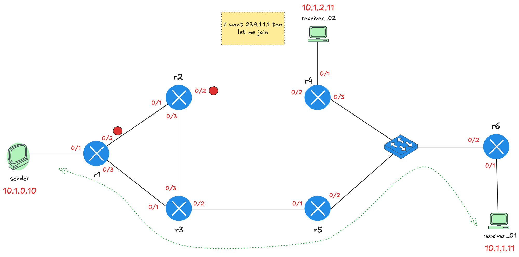
Let's continue with our testing. At present, the sender is sending multicast traffic to 239.1.1.1 and receiver_01 has joined the group. We already see the top path through r2 and r4 is pruned, indicated by the red dots on the interfaces. Now let's also make receiver_02 join the group. I am taking packet captures between r4 and r2, specifically on r4's Ethernet0/2 interface.
receiver_02(config)#interface et0/1
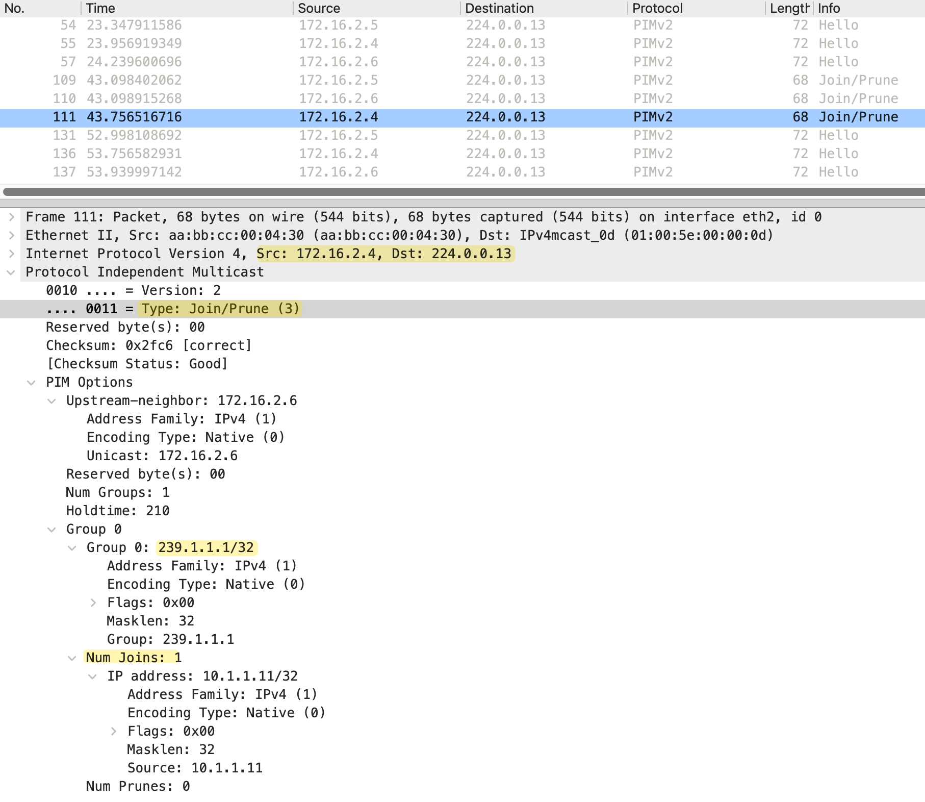
receiver_02(config-if)#ip igmp join-group 239.1.1.1When receiver_02 joins the multicast group, r4 needs to start receiving the multicast traffic. Since the path toward r2 was previously pruned, r4 sends a Graft message to r2 requesting the traffic. As we can see in the debug messages/packet capture below, the Graft message is sent from 172.16.1.10 (r4) to 172.16.1.9 (r2). The message type is Graft (6) and includes the upstream neighbor 172.16.1.9, which is r2. The group address is 239.1.1.1 with Num Joins set to 1.
#r4

PIM(0)[default]: Join-list: (10.1.0.10/32, 239.1.1.1)
PIM(0)[default]: Building Graft message for 239.1.1.1, Ethernet0/1: no entries
PIM(0)[default]: Building Graft message for 239.1.1.1, Ethernet0/3: no entries
PIM(0)[default]: Building Graft message for 239.1.1.1, Ethernet0/2: 10.1.0.10/32 count 1
PIM(0)[default]: Send v2 Graft to 172.16.1.9 (Ethernet0/2)
PIM(0)[default]: Received v2 Graft-Ack on Ethernet0/2 from 172.16.1.9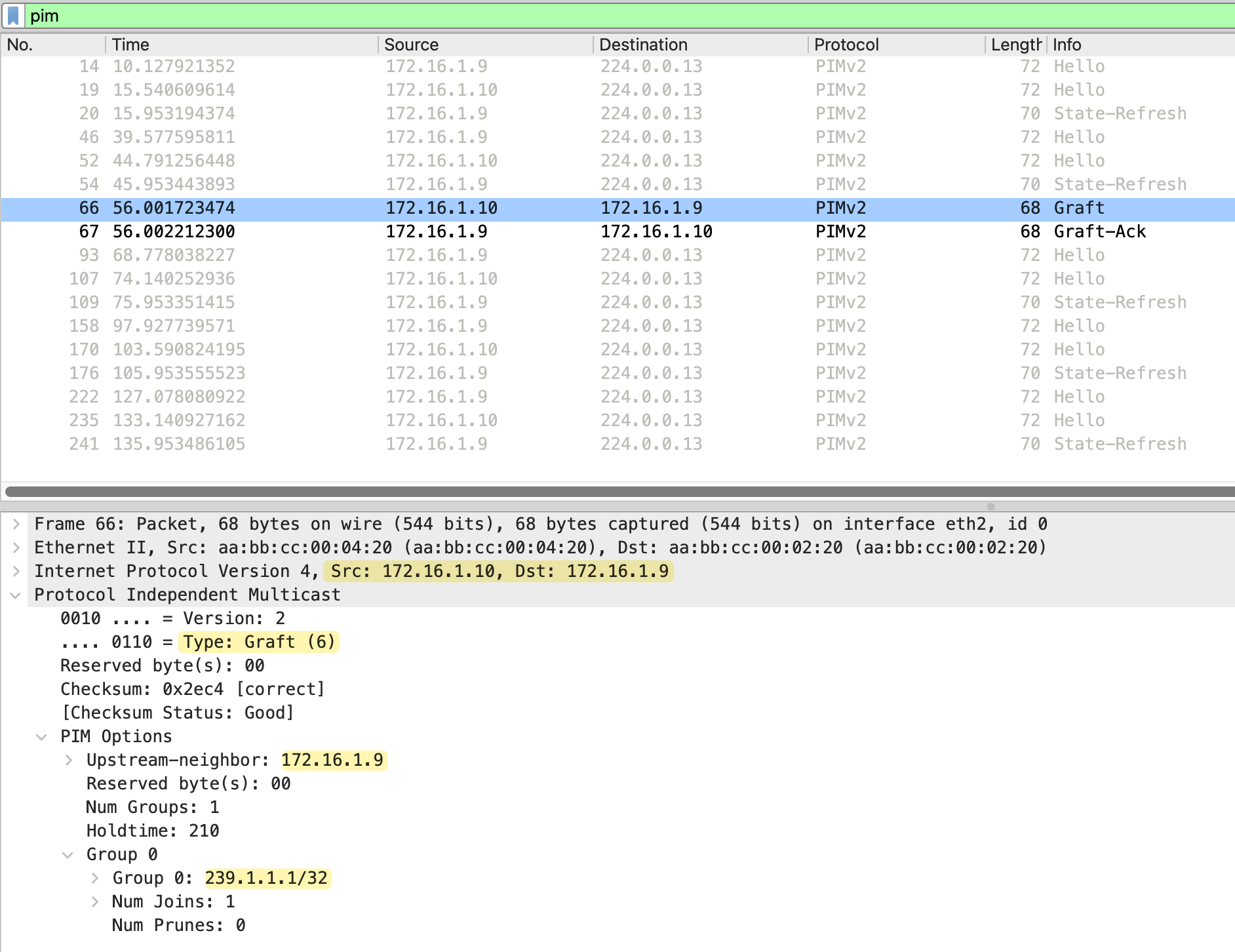
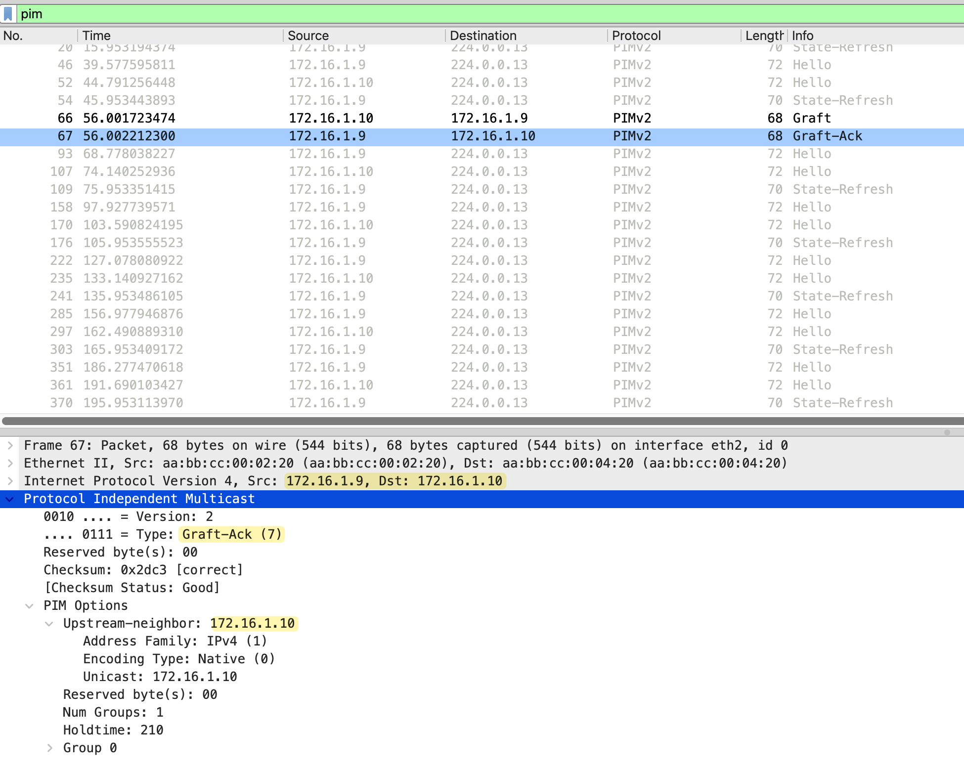
Immediately after receiving the Graft, r2 responds with a Graft-Ack message. This is sent from 172.16.1.9 (r2) back to 172.16.1.10 (r4). The message type is Graft-Ack (7), confirming that r2 has received the Graft and will resume forwarding multicast traffic to r4.
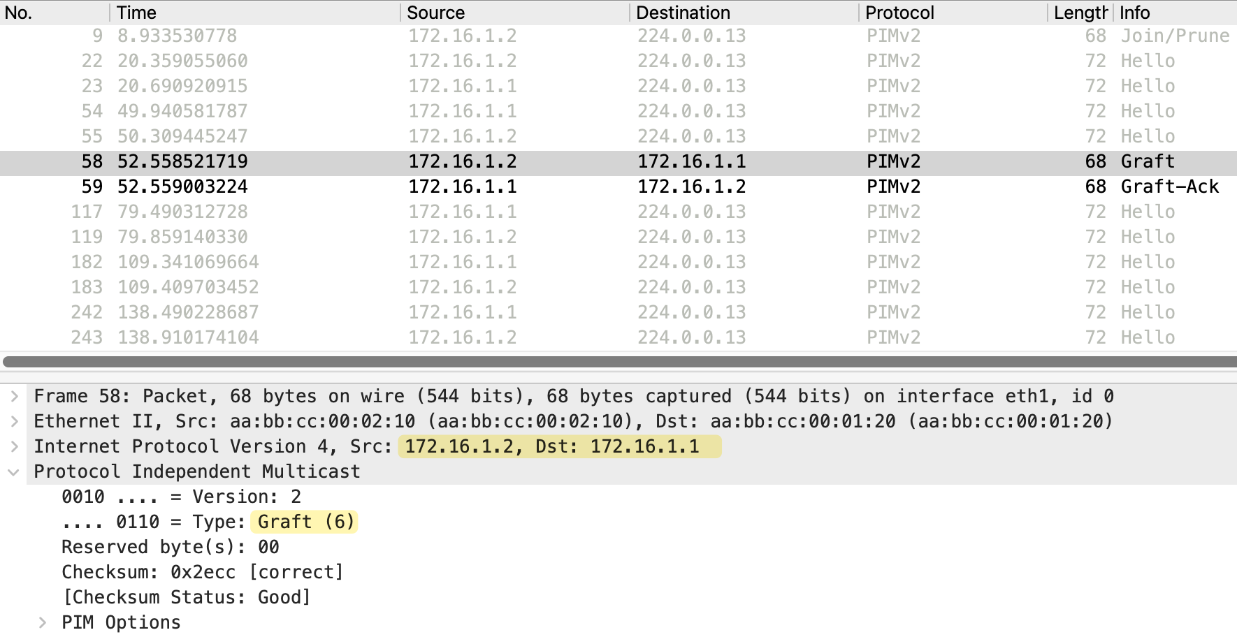
The same process happens from r2 to r1 as well. Since the link between r1 and r2 was also pruned, r2 sends a Graft message to r1 requesting the multicast traffic. r1 responds with a Graft-Ack and adds the interface toward r2 back to its outgoing interface list. Now the multicast traffic flows through both paths, the lower path via r3 and r5 to receiver_01, and the upper path via r2 and r4 to receiver_02.
PIM Override
PIM Override is a mechanism used when multiple routers share the same LAN segment. When one router on the segment sends a Prune message, other routers that still have interested receivers need a way to prevent the upstream router from pruning the interface.
We made a small adjustment to the topology and moved the sender behind r6. Both receiver_01 and receiver_02 have joined the multicast group, and r6 is forwarding traffic toward both r4 and r5 through the shared switch segment.
Now, let's say receiver_02 decides to leave the group. When this happens, r5 no longer has any interested receivers, so it sends a Prune message toward r6 on the shared segment.
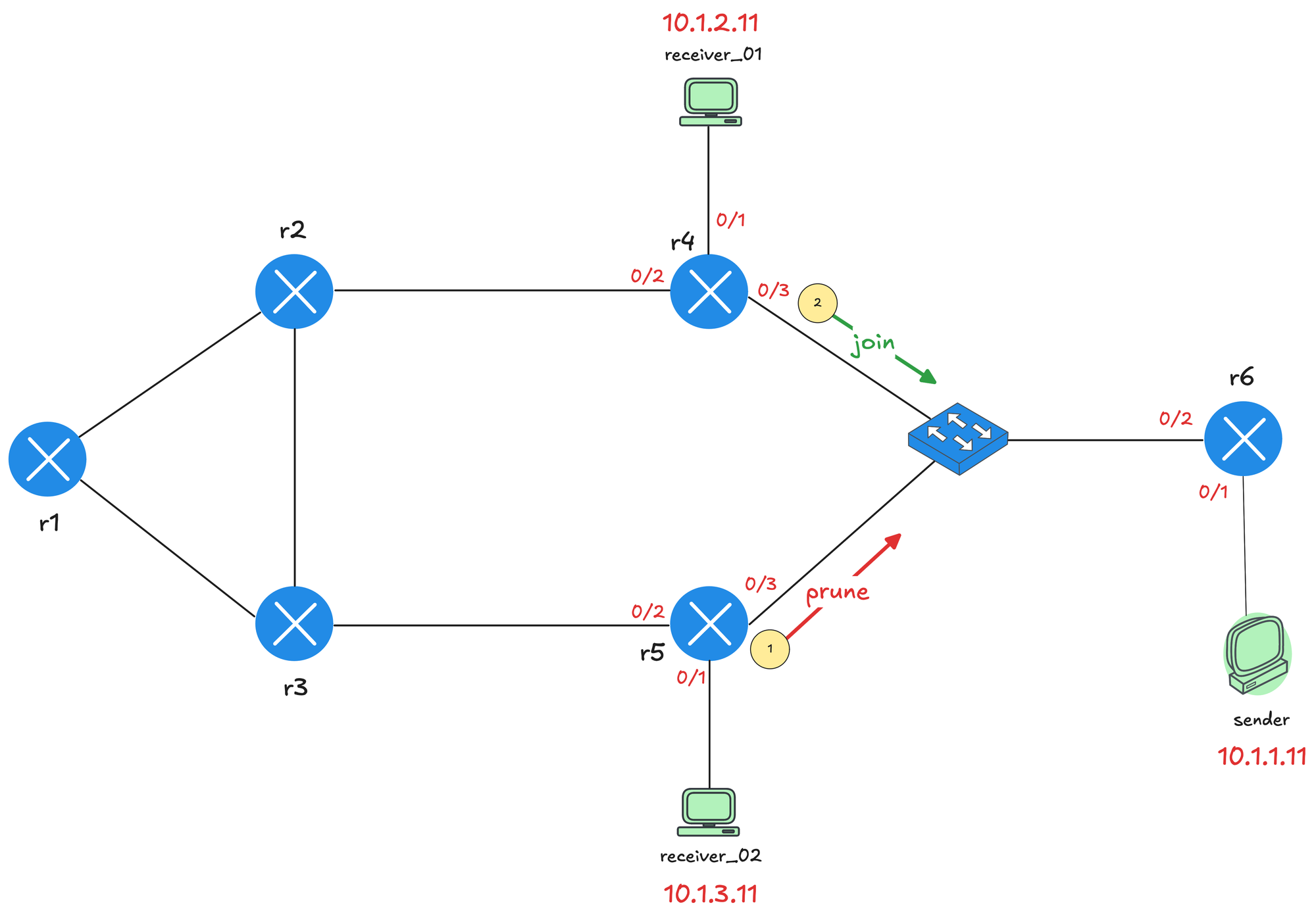
However, r4 still has receiver_01 connected and needs the multicast traffic to continue flowing. When r4 sees the Prune message from r5 on the shared segment, it sends a PIM Join message before the prune takes effect.
This Join (from r4) overrides the Prune and tells r6 to continue forwarding multicast traffic on that segment. Without this override mechanism, r6 would stop sending traffic and receiver_01 would lose the multicast stream even though it is still interested. Here is a debug message from r6 that shows both the prune from r5 (172.16.2.5) and join from r4 (172.16.2.4).
#r6

Received v2 Join/Prune on Ethernet0/2 from 172.16.2.5, to us
Prune-list: (10.1.1.11/32, 239.1.1.1)
Schedule to prune Ethernet0/2 for (10.1.1.11/32, 239.1.1.1)
Received v2 Join/Prune on Ethernet0/2 from 172.16.2.4, to us
Join-list: (10.1.1.11/32, 239.1.1.1)
MIDB Update Ethernet0/2/172.16.2.4 to (10.1.1.11, 239.1.1.1),
Forward state, by PIM SG Join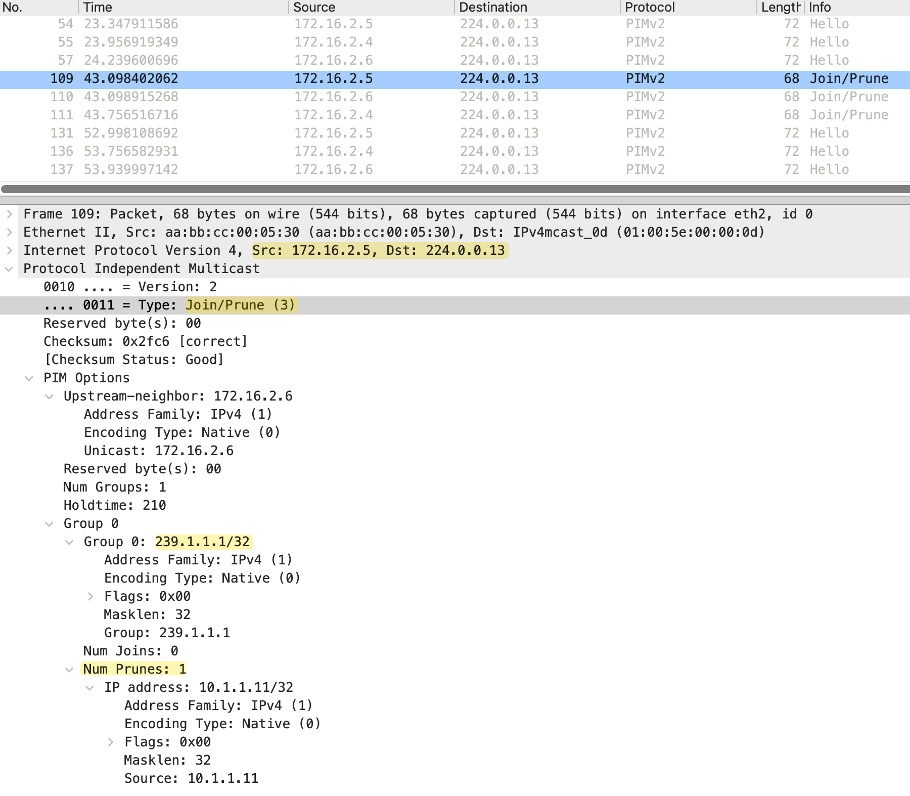
r4 does not send the Join immediately. Instead, it starts a short delay timer called the prune override interval (less than the prune delay timer of 3 seconds). The purpose of this delay is to prevent multiple routers from sending Join messages at the same time if there are several routers on the segment that still need the traffic. If another router on the segment sends a Join before the timer expires, r4 cancels its own Join since the override has already been sent. This keeps PIM traffic to a minimum while still ensuring the prune gets overridden.
#r4

Received v2 Join/Prune on Ethernet0/3 from 172.16.2.5, not to us
Prune-list: (10.1.1.11/32, 239.1.1.1)
Set join delay timer to 700 msec for (10.1.1.11/32, 239.1.1.1) on Ethernet0/3
Received v2 Join/Prune on Ethernet0/3 from 172.16.2.6, not to us
Prune-list: (10.1.1.11/32, 239.1.1.1)
Join delay timer running at 600 for (10.1.1.11, 239.1.1.1) on Ethernet0/3
Insert (10.1.1.11,239.1.1.1) join in nbr 172.16.2.6's queue
Building Join/Prune packet for nbr 172.16.2.6
Adding v2 (10.1.1.11/32, 239.1.1.1) Join, RLOC_G: 0.0.0.0
Send v2 join/prune to 172.16.2.6 (Ethernet0/3)
PIM Join/Prune Message
As we briefly mentioned earlier, PIM does not have separate message types for Join and Prune. Instead, it uses a single Join/Prune message that can carry both join and prune information in the same packet. This is the same message format we saw earlier when looking at the Prune packet capture.
The Join/Prune message includes the upstream neighbor address, which identifies the router the message is intended for. It also includes a Num Groups field that specifies how many multicast groups are included in the message. For each group, there is a Num Joins field indicating how many sources to join and a Num Prunes field indicating how many sources to prune. If a router wants to join a group, the source is listed under the joins. If a router wants to prune, the source is listed under the prunes.
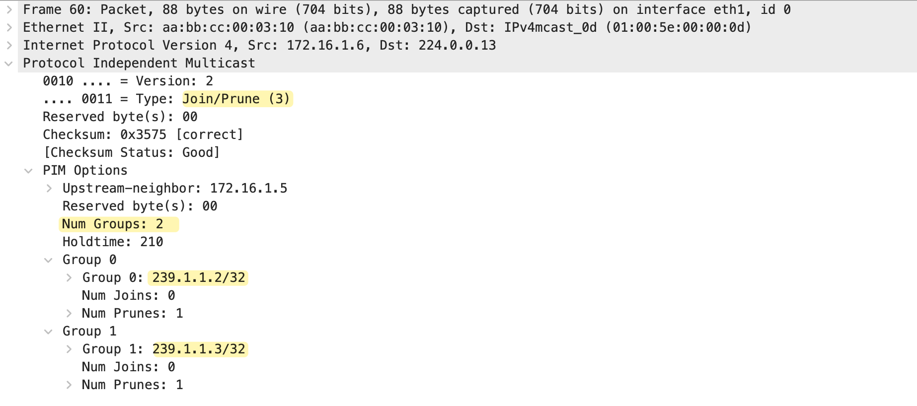
A single Join/Prune message can also contain multiple groups. In the packet capture above, we can see Num Groups is set to 2. The message includes
- Group 0 for 239.1.1.2
- Group 1 for 239.1.1.3
Both with Num Joins set to 0 and Num Prunes set to 1. This allows a router to prune (or join) multiple multicast groups in a single message rather than sending separate messages for each group.