

In the previous post, we covered PIM Dense Mode and mentioned that it is not widely used in production because of its flood and prune behaviour. Every router in the network receives the multicast traffic first, and then routers without interested receivers have to send prune messages. This is inefficient, especially in large networks.

In this post, we will look at PIM Sparse Mode, which takes the opposite approach. Instead of flooding traffic everywhere and pruning where it is not needed, Sparse Mode only sends traffic to parts of the network that explicitly request it. Routers with interested receivers send Join messages and only then does the multicast traffic start flowing. This makes Sparse Mode much more efficient and scalable, which is why it is the preferred mode in most production networks today.
PIM Spare Mode Overview
In Dense Mode, we saw two main problems. Multicast traffic is flooded everywhere, and every router has to maintain state for every multicast group, even if all its interfaces are pruned. Sparse Mode solves both of these problems by only sending traffic where it is explicitly requested. Routers that are not in the path do not keep any state. However, this introduces a new challenge. If we are not flooding, how does a receiver know where to find the source? And how does the source know where the receivers are?
PIM Sparse Mode relies on a central point in the network called the Rendezvous Point, or RP. The RP acts as a meeting point between sources and receivers. When a receiver wants to join a multicast group, the last hop router sends a Join message toward the RP. When a source starts sending multicast traffic, the first hop router registers the source with the RP. The RP then connects the two, allowing traffic to flow from the source to the receivers.

Initially, multicast traffic flows through the RP. This is called the shared tree or RP tree, often written as (*,G). Once traffic starts flowing, routers can optionally switch to a Shortest Path Tree (SPT), also written as (S,G), which goes directly from the source to the receivers without passing through the RP. This switch happens automatically when the traffic rate exceeds a certain threshold, and it provides a more optimal path for the multicast traffic.
Okay, What is a Rendezvous Point (RP)?
The Rendezvous Point is just another router (with a bit of extra responsibilities) in the network that acts as the meeting point for multicast sources and receivers. When a source starts sending multicast traffic, it does not flood the traffic everywhere like in Dense Mode. Instead, the first hop router encapsulates the first multicast packet and sends it as unicast to the RP. This message is called PIM Register. If there are receivers joined to the group, the RP decapsulates the traffic and forwards it down the shared tree. The RP also builds a source tree back toward the first hop router so it can receive native multicast traffic. Once that path is ready, the RP tells the first hop router to stop encapsulating, and traffic flows natively to the RP.
On the receiver side, when a host wants to join a multicast group, the last hop router sends a PIM Join message toward the RP. This Join travels hop by hop, and each router along the path adds the interface to its outgoing interface list for that group. Once the Join reaches the RP, the path is established, and traffic can flow from the RP down to the receiver.
Any router in the network can be configured as the RP, but it should be a well-connected router since all multicast traffic initially passes through it. In a real network, you typically have redundancy with multiple RPs or use a mechanism like Auto-RP or Bootstrap Router (BSR) to dynamically elect the RP. We will cover RP election mechanisms later in this series.
PIM Spare Mode Topology
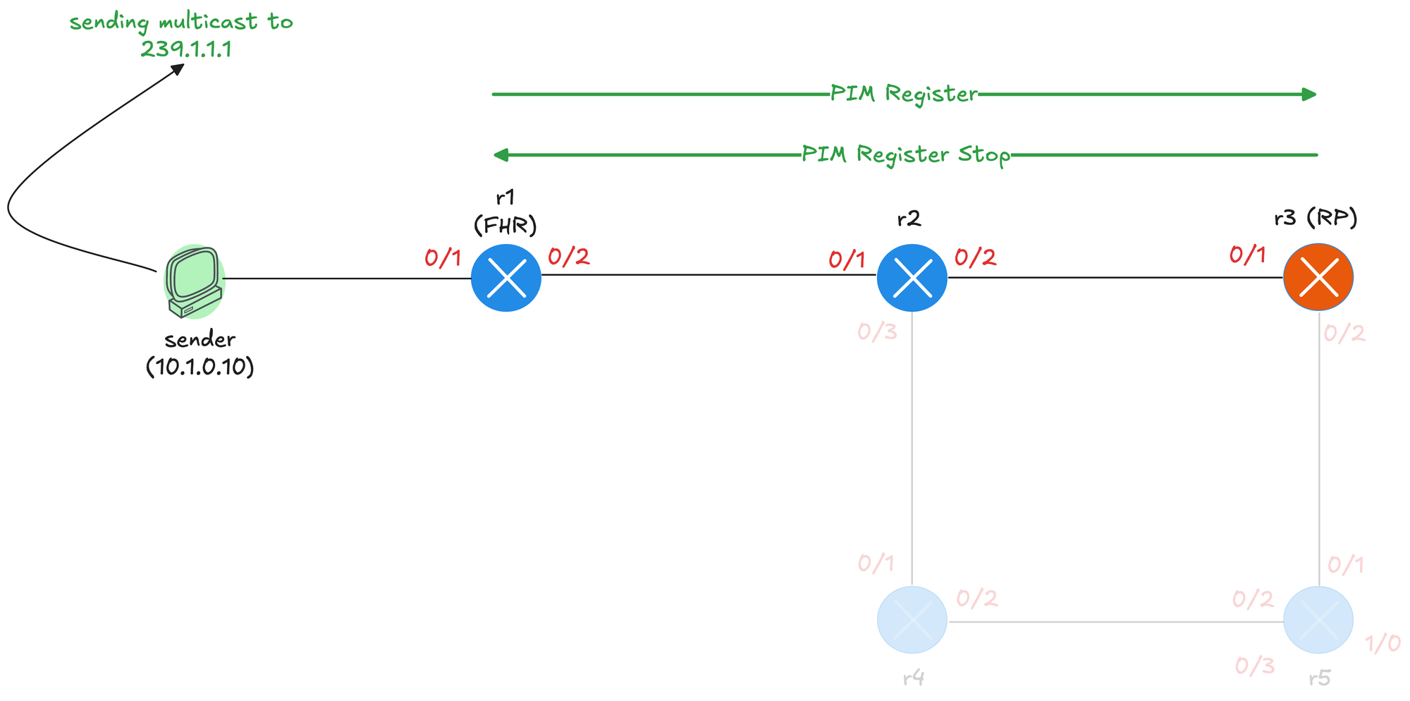
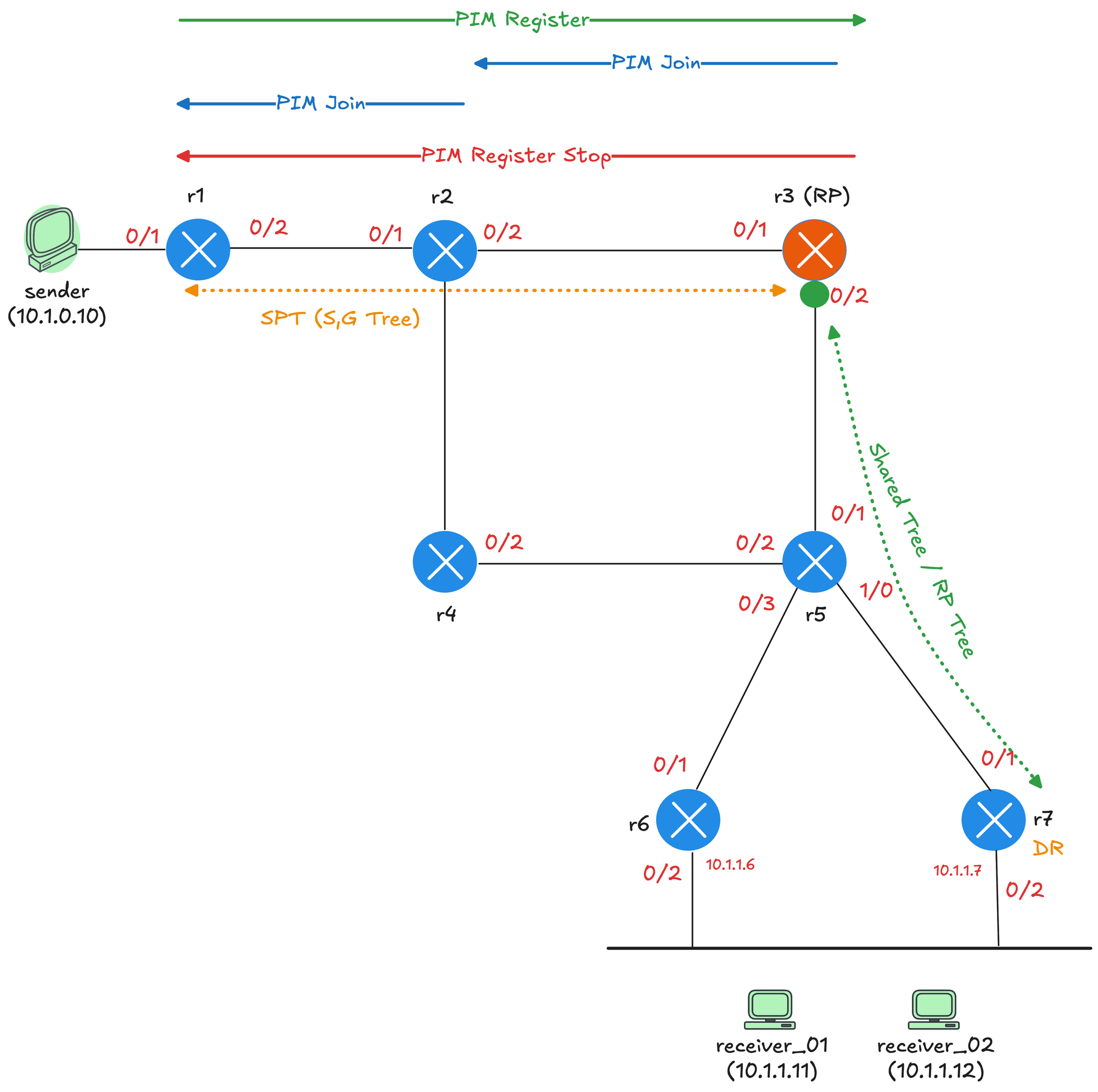
Let's take a step back from the theory and look at a practical example. Our example is based on the topology shown below. The sender is connected to r1, which acts as the first hop router (FHR). r3 is configured as the Rendezvous Point. Below r5, we have r6 and r7 connecting to a shared segment where receiver_01 and receiver_02 are located. There is a reason why we have a share segment here because we need to cover the concept of Designated Router (DR) later in this post.

You can rebuild this topology using Netlab with a single command. I will include the topology file below. I covered Netlab in detail in a previous post, which is linked below.
Each router has a loopback interface with IP address 10.0.0.x, where x is the router number. For example, r1 has 10.0.0.1, r2 has 10.0.0.2, and so on. We configure r3's loopback address 10.0.0.3 as the RP and tell every router in the network that 10.0.0.3 is the RP for all multicast groups. We are using a static RP configuration to keep things simple.
You don't have to use a loopback address for the RP, but it is a common practice. The loopback interface is always up as long as the router is running, so it provides a stable address that does not depend on any physical interface. If you use a physical interface and that interface goes down, the RP becomes unreachable even if the router itself is still operational and has other working paths.
In terms of configuration, we covered this in detail in the previous post on PIM Dense Mode. As usual, we enable ip multicast-routing globally and disable Auto RP so the output and debugs are clear and exclude the Auto RP multicast addresses. We also have OSPF enabled on all the interfaces so we have unicast routing in place. The sender and receivers can ping each other using their unicast IP addresses.
!r3 config

interface Loopback0
 ip address 10.0.0.3 255.255.255.255
 ip pim sparse-mode
 ip ospf 1 area 0.0.0.0
!
interface Ethernet0/1
 description r3 -> r2
 ip address 172.16.1.6 255.255.255.252
 ip pim sparse-mode
 ip ospf network point-to-point
 ip ospf 1 area 0.0.0.0
!
interface Ethernet0/2
 description r3 -> r5
 ip address 172.16.1.13 255.255.255.252
 ip pim sparse-mode
 ip ospf network point-to-point
 ip ospf 1 area 0.0.0.0
!
router ospf 1
 router-id 10.0.0.3
!
ip multicast-routing
no ip pim autorp
ip pim rp-address 10.0.0.3
The notable difference from Dense Mode is that under each interface we now have sparse-mode enabled instead of dense-mode. On r3, we also enable sparse-mode on the loopback interface since this is the RP address. We then statically configure the RP using ip pim rp-address 10.0.0.3. To make r3 the RP, we simply point the RP address to its own loopback. The same command is applied on all other routers so they know where to find the RP.
The other routers have the exact same configuration, except you do not need to enable pim sparse-mode on their loopback interfaces. For reference, here is the config from r1.
!r1 config

interface Loopback0
 ip address 10.0.0.1 255.255.255.255
 ip ospf 1 area 0.0.0.0
!
interface Ethernet0/1
 description r1 -> sender
 ip address 10.1.0.1 255.255.255.0
 ip pim sparse-mode
 ip ospf network point-to-point
 ip ospf 1 area 0.0.0.0
!
interface Ethernet0/2
 description r1 -> r2
 ip address 172.16.1.1 255.255.255.252
 ip pim sparse-mode
 ip ospf network point-to-point
 ip ospf 1 area 0.0.0.0
!
router ospf 1
 router-id 10.0.0.1
 passive-interface Ethernet0/1
!
!
ip multicast-routing
no ip pim autorp
ip pim rp-address 10.0.0.3
As soon as you configure the RP, you will see tunnel interfaces being created automatically. On the RP itself, you will see two tunnels. On every other router in the network, you will see one tunnel. These tunnels are used for the PIM register process, which we will cover shortly when we look at how the source registers with the RP.
r3#show interfaces description  | incl Tu
Tu0     up        up       Pim Register Tunnel (Encap) for RP 10.0.0.3
Tu1     up        up       Pim Register Tunnel (Decap) for RP 10.0.0.3
r3#show ip interface brief | incl Tu
Tunnel0 10.0.0.3 YES unset up up
Tunnel1 10.0.0.3 YES unset up upr1#show ip interface brief | incl Tu
Tunnel0 172.16.1.1 YES unset up upYou can check who the RP is by running the following command.
r1#show ip pim rp mapping
Auto-RP is not enabled
PIM Group-to-RP Mappings

Group(s): 224.0.0.0/4, Static
    RP: 10.0.0.3 (r3)
PIM Neighbours
Before we go further, let's quickly cover PIM neighbors even though we covered this in detail in PIM Dense Mode. Just like in Dense Mode, routers running PIM Sparse Mode send Hello messages to discover neighbors. These Hellos are sent to the multicast address 224.0.0.13 every 30 seconds. When two routers exchange Hellos, they form a neighbor relationship and can then exchange other PIM messages like Joins and Prunes.
You can verify PIM neighbors using the show ip pim neighbor command. This shows the neighbor IP address, the interface where the neighbor was learned, how long the neighbor has been up, and when it will expire if no more Hellos are received.
r2#show ip pim neighbor
PIM Neighbor Table
Mode: B - Bidir Capable, DR - Designated Router, N - Default DR Priority,
      P - Proxy Capable, S - State Refresh Capable, G - GenID Capable,
      L - DR Load-balancing Capable
Neighbor          Interface                Uptime/Expires    Ver   DR
Address                                                            Prio/Mode
172.16.1.1        Ethernet0/1              02:33:02/00:01:42 v2    1/S P G
172.16.1.6        Ethernet0/2              02:32:58/00:01:41 v2    1/DR S P G
172.16.1.10       Ethernet0/3              02:32:50/00:01:20 v2    1/DR S P G
PIM neighbors are essential for building the multicast distribution tree. When a router needs to send a Join or Prune message, it sends it toward the upstream neighbor in the direction of the RP or source. Without a neighbor relationship, routers cannot exchange these PIM messages, and the multicast tree cannot be built. The neighbor relationship also helps routers detect failures. If a router stops receiving Hello messages from a neighbor and the hold timer expires, it removes that neighbor and updates its multicast forwarding state accordingly.
PIM Sparse Mode Scenarios
So we have all the configurations in place. Now let's look at various scenarios to understand how exactly PIM Sparse Mode works. We will start with a scenario where there are receivers, but no source is sending any multicast traffic yet.
1 - Receivers Without a Source
Let's make receiver_01 join the multicast group 239.1.1.1. At this point, there is no source sending any traffic yet. When receiver_01 sends an IGMP Membership Report for 239.1.1.1, the report reaches both r6 and r7 since they are both connected to the same segment. However, only one of these routers should send the PIM Join toward the RP. This is where the Designated Router comes in.
receiver_01(config)#interface Et0/1
receiver_01(config-if)#ip igmp join-group 239.1.1.1
The Designated Router, or DR, is elected on every multi-access segment where PIM is enabled. The DR is responsible for sending PIM Join messages toward the RP on behalf of receivers on that segment. The election is based on DR priority first, and if the priority is the same, the router with the highest IP address wins. In this example, r6's Ethernet0/2 interface (the one on the LAN segment) has IP address 10.1.1.6, and r7's Ethernet0/2 has 10.1.1.7. Since r7 has the higher IP address, it wins the DR election and becomes responsible for sending the Join toward the RP. You can check who the RP is by running the following commands.
r6#show ip pim neighbor
PIM Neighbor Table
Mode: B - Bidir Capable, DR - Designated Router, N - Default DR Priority,
      P - Proxy Capable, S - State Refresh Capable, G - GenID Capable,
      L - DR Load-balancing Capable
Neighbor          Interface                Uptime/Expires    Ver   DR
Address                                                            Prio/Mode
172.16.1.21       Ethernet0/1              00:08:09/00:01:28 v2    1 / S P G
10.1.1.7          Ethernet0/2              00:08:05/00:01:31 v2    1 / DR S P G
r6#show ip pim interface Ethernet0/2 detail
Ethernet0/2 is up, line protocol is up
Internet address is 10.1.1.6/24
Multicast switching: fast
Multicast packets in/out: 0/0
Multicast TTL threshold: 0
PIM: enabled
PIM version: 2, mode: sparse
PIM DR: 10.1.1.7
PIM neighbor count: 1
PIM Hello/Query interval: 30 seconds
PIM Hello packets in/out: 23/23
PIM J/P interval: 60 seconds
PIM State-Refresh processing: enabled
PIM State-Refresh origination: disabled
PIM NBMA mode: disabled
PIM ATM multipoint signalling: disabled
PIM domain border: disabled
PIM neighbors rpf proxy capable: TRUE
PIM BFD: disabled
PIM Non-DR-Join: FALSE
Multicast Tagswitching: disabledWhen receiver_01 joins the group, r7, the DR sends a PIM Join message toward the RP. Here is the debug from r7.
r7# debug ip pim

PIM(0)[default]: Re-check RP 10.0.0.3 into the (*, 239.1.1.1) entry
PIM(0)[default]: Building Triggered (*,G) Join / (S,G,RP-bit) Prune message for 239.1.1.1
PIM(0)[default]: Building Triggered (*,G) Join / (S,G,RP-bit) Prune message for 239.1.1.1
PIM(0)[default]: Upstream mode for (*, 239.1.1.1) changed from 0 to 1
PIM(0)[default]: Insert (*,239.1.1.1) join in nbr 172.16.1.25's queue
PIM(0)[default]: Building Join/Prune packet for nbr 172.16.1.25
PIM(0)[default]:  Adding v2 (10.0.0.3/32, 239.1.1.1), WC-bit, RPT-bit, S-bit Join, RLOC_G: 0.0.0.0
PIM(0)[default]: Send v2 join/prune to 172.16.1.25 (Ethernet0/1)
The Join is sent hop by hop, from r7 to r5, and then from r5 to r3, which is the RP. Each router along the path creates a (*,G) entry on their multicast route table and adds the interface where it received the Join to its outgoing interface list (OIL). In the (*,G) entry, the incoming interface is the interface pointing toward the RP. Each router along the shared tree uses its unicast routing table to determine which interface is the best path to reach the RP address. This interface becomes the incoming interface for the entry. Traffic for this group is expected to arrive on this interface.
r7#show ip mroute
IP Multicast Routing Table

(*, 239.1.1.1), 00:00:43/00:02:41, RP 10.0.0.3, flags: SJC
  Incoming interface: Ethernet0/1, RPF nbr 172.16.1.25
  Outgoing interface list:
    Ethernet0/2, Forward/Sparse, 00:00:43/00:02:41, flags:
r5#show ip mroute
IP Multicast Routing Table
(*, 239.1.1.1), 00:00:48/00:02:41, RP 10.0.0.3, flags: S
Incoming interface: Ethernet0/1, RPF nbr 172.16.1.13
Outgoing interface list:
Ethernet1/0, Forward/Sparse, 00:00:48/00:02:41, flags: This builds the shared tree from the RP down to the receiver, even though no traffic is flowing yet. Here is the debug seen on r3.
r3#debug ip pim

PIM(0)[default]: Received v2 Join/Prune on Ethernet0/2 from 172.16.1.14, to us
PIM(0)[default]: Join-list: (*, 239.1.1.1), RPT-bit set, WC-bit set, S-bit set
PIM(0)[default]: Re-check RP 10.0.0.3 into the (*, 239.1.1.1) entry
PIM(0)[default]: Tunnel1 locked on (0.0.0.0,239.1.1.1), lock TUN_MODE_PIM_DEC_IPV4_default refcnt 1, mdb [0]:TUN_MODE_PIM_DEC_IPV4_default [1]:
PIM(0)[default]: Adding register decap tunnel (Tunnel1) as accepting interface of (*, 239.1.1.1).
PIM(0)[default]: MIDB Add Ethernet0/2/172.16.1.14 to (*, 239.1.1.1), Forward state, by PIM *G Join
r3#show ip mroute
IP Multicast Routing Table
(*, 239.1.1.1), 00:00:52/00:02:37, RP 10.0.0.3, flags: S
Incoming interface: Null, RPF nbr 0.0.0.0
Outgoing interface list:
Ethernet0/2, Forward/Sparse, 00:00:52/00:02:37, flags: To recap, diagram below shows what happens when receiver_01 joins the multicast group 239.1.1.1 with no source sending traffic yet. r7 is the DR for the receiver segment since it has the higher IP address (10.1.1.7 compared to r6's 10.1.1.6). When receiver_01 sends an IGMP report, r7 sends a PIM Join toward the RP. The Join travels from r7 to r5, and then from r5 to r3, which is the RP.
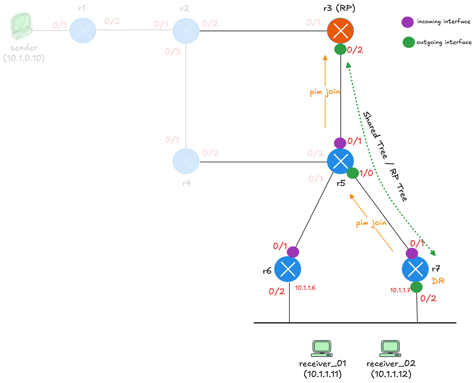
As the Join travels upstream, each router creates a (*,G) entry. The purple dots represent the incoming interface on each router, which is the interface pointing toward the RP. The green dots represent the outgoing interface, which is the interface where the Join was received from. This builds the shared tree, shown by the green dotted line, from the RP down to the receiver. Notice that r1, r2, and r4 are faded out in the diagram. These routers are not part of the shared tree because they are not in the path between the RP and the receivers.
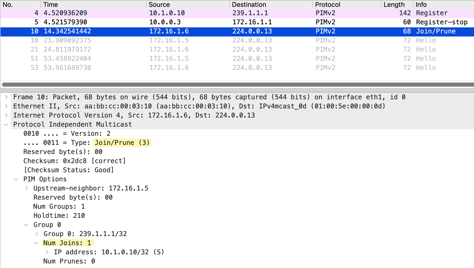
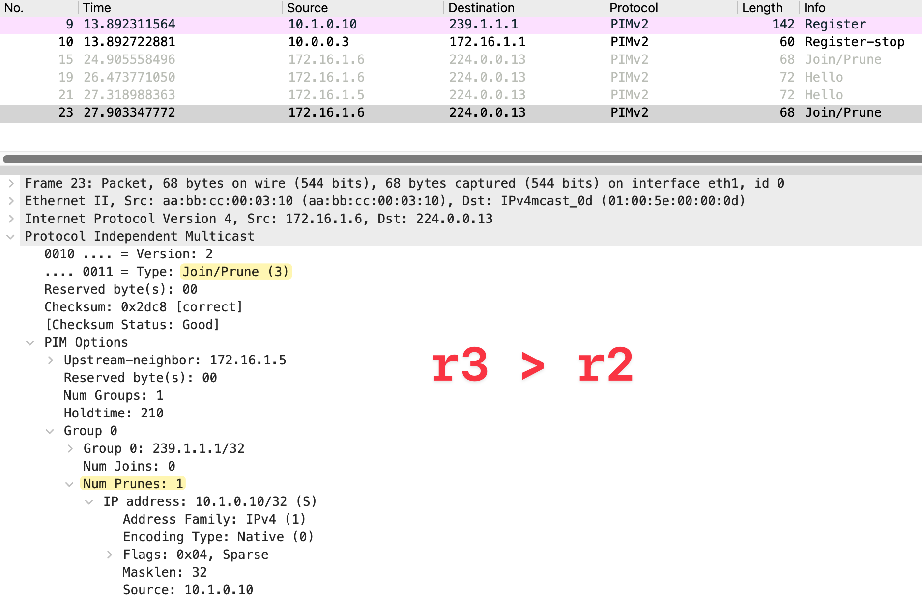
The packet capture below shows the PIM Join message sent from r7 to r5. The source IP is 172.16.1.26, which is r7's Ethernet0/1 interface, and the destination is 224.0.0.13, the all PIM routers address.
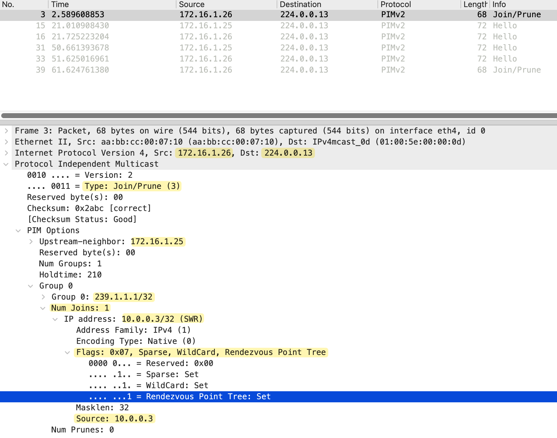
Looking at the PIM message details, the Type is Join/Prune (3) and the upstream neighbor is set to 172.16.1.25, which is r5's Ethernet1/0 interface. The Num Groups is 1, indicating this Join is for a single multicast group.
Under Group 0, we can see the multicast group address 239.1.1.1/32. The Num Joins is 1 and Num Prunes is 0, confirming this is a Join message. The IP address in the join list is 10.0.0.3, which is the RP address. The flags show Sparse, WildCard, and Rendezvous Point Tree are all set. This indicates that this is a (*,G) Join toward the RP to join the shared tree. The WildCard flag means any source, and the Rendezvous Point Tree flag confirms this Join is for the shared tree rooted at the RP.
2 - Active Source Without Receivers
Now let's look at the opposite scenario. We have a source actively sending multicast traffic, but there are no receivers joined to the group yet. This will help us understand how the source registers with the RP and what happens to the traffic when no one is listening. First, I am going to make receiver_01 leave the multicast group so we have no receivers in the network.
receiver_01(config)#interface Et0/1
receiver_01(config-if)#no ip igmp join-group 239.1.1.1
sender#ping 239.1.1.1 repeat 200When the sender starts sending multicast traffic to 239.1.1.1, the packets arrive at r1, which is the first hop router (FHR). r1 creates an (S,G) entry and also needs to inform the RP about this new source. This is done through the PIM Register process.
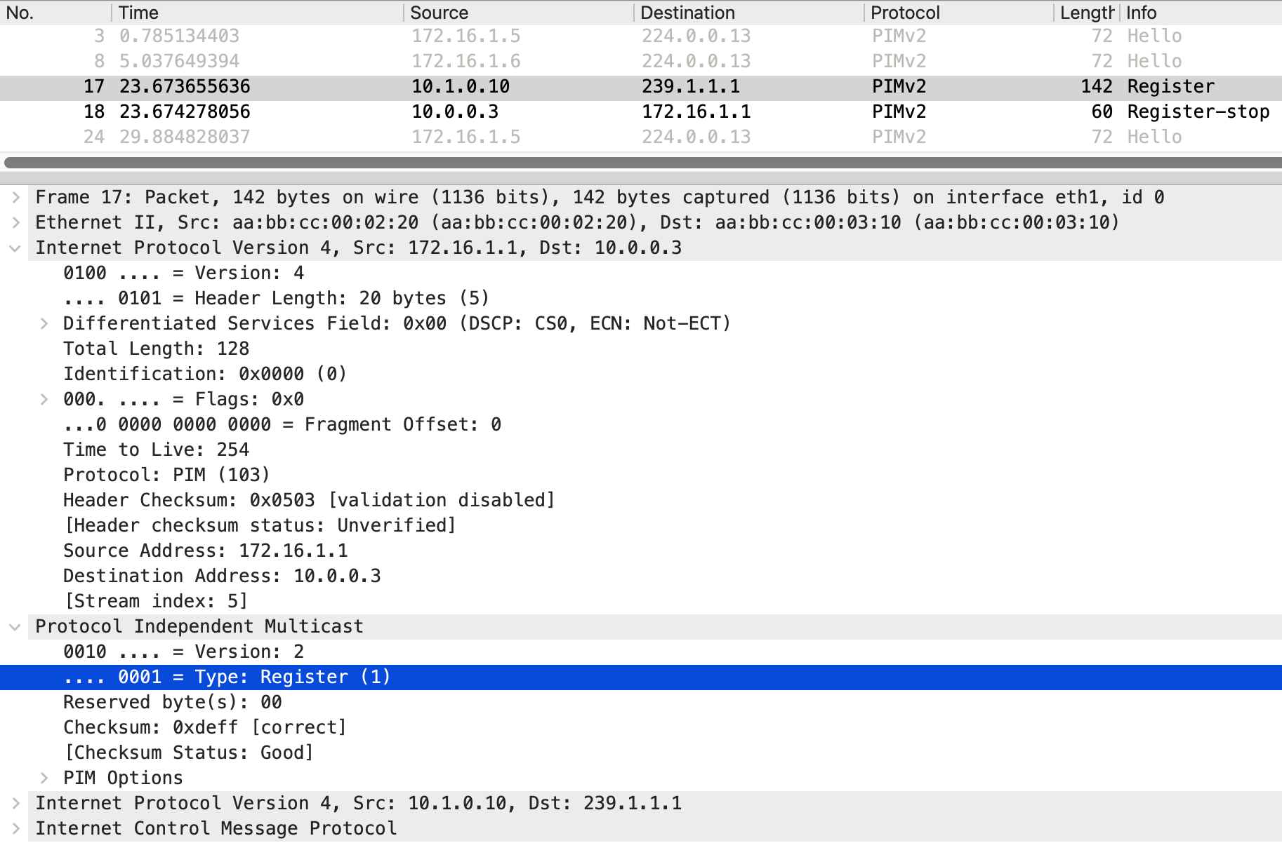
r1 encapsulates the original multicast packet inside a PIM Register message and sends it as unicast directly to the RP at 10.0.0.3.
r1#debug ip pim

Re-check RP 10.0.0.3 into the (*, 239.1.1.1) entry
Building Triggered (*,G) Join / (S,G,RP-bit) Prune message for 239.1.1.1
Tunnel0 locked on (10.1.0.10,239.1.1.1), lock TUN_MODE_PIM_ENC_IPV4_default refcnt 1, mdb [0]:TUN_MODE_PIM_ENC_IPV4_default [1]:
Adding register encap tunnel (Tunnel0) as forwarding interface of (10.1.0.10, 239.1.1.1).
Looking at the packet capture below, we can see the outer IP header has a source of 172.16.1.1 (r1) and a destination of 10.0.0.3 (the RP).
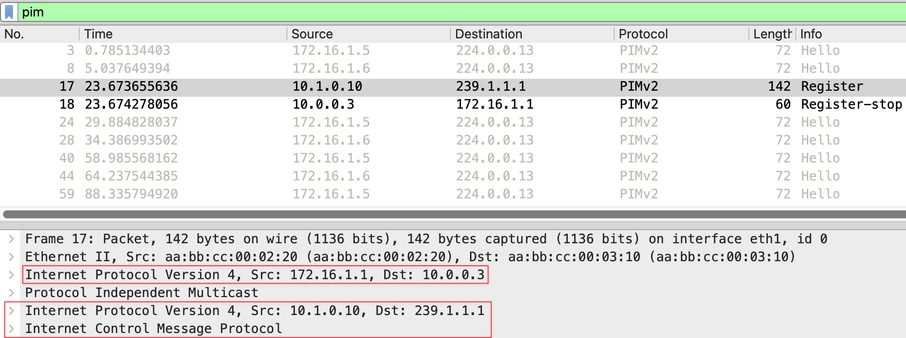
The PIM message type is Register (1). Inside this Register message, the original multicast packet is encapsulated. You can see the inner IP header showing source 10.1.0.10 (the sender) and destination 239.1.1.1 (the multicast group), along with the ICMP payload from our ping.
r3#debug ip pim
Received v2 Register on Ethernet0/1 from 172.16.1.1 for 10.1.0.10, group 239.1.1.1
Re-check RP 10.0.0.3 into the (*, 239.1.1.1) entry
Tunnel1 locked on (0.0.0.0,239.1.1.1), lock TUN_MODE_PIM_DEC_IPV4_default refcnt 1, mdb [0]:TUN_MODE_PIM_DEC_IPV4_default [1]:
Adding register decap tunnel (Tunnel1) as accepting interface of (*, 239.1.1.1).
Tunnel1 locked on (10.1.0.10,239.1.1.1), lock TUN_MODE_PIM_DEC_IPV4_default refcnt 2, mdb [0]:TUN_MODE_PIM_DEC_IPV4_default [1]:
Adding register decap tunnel (Tunnel1) as accepting interface of (10.1.0.10, 239.1.1.1)
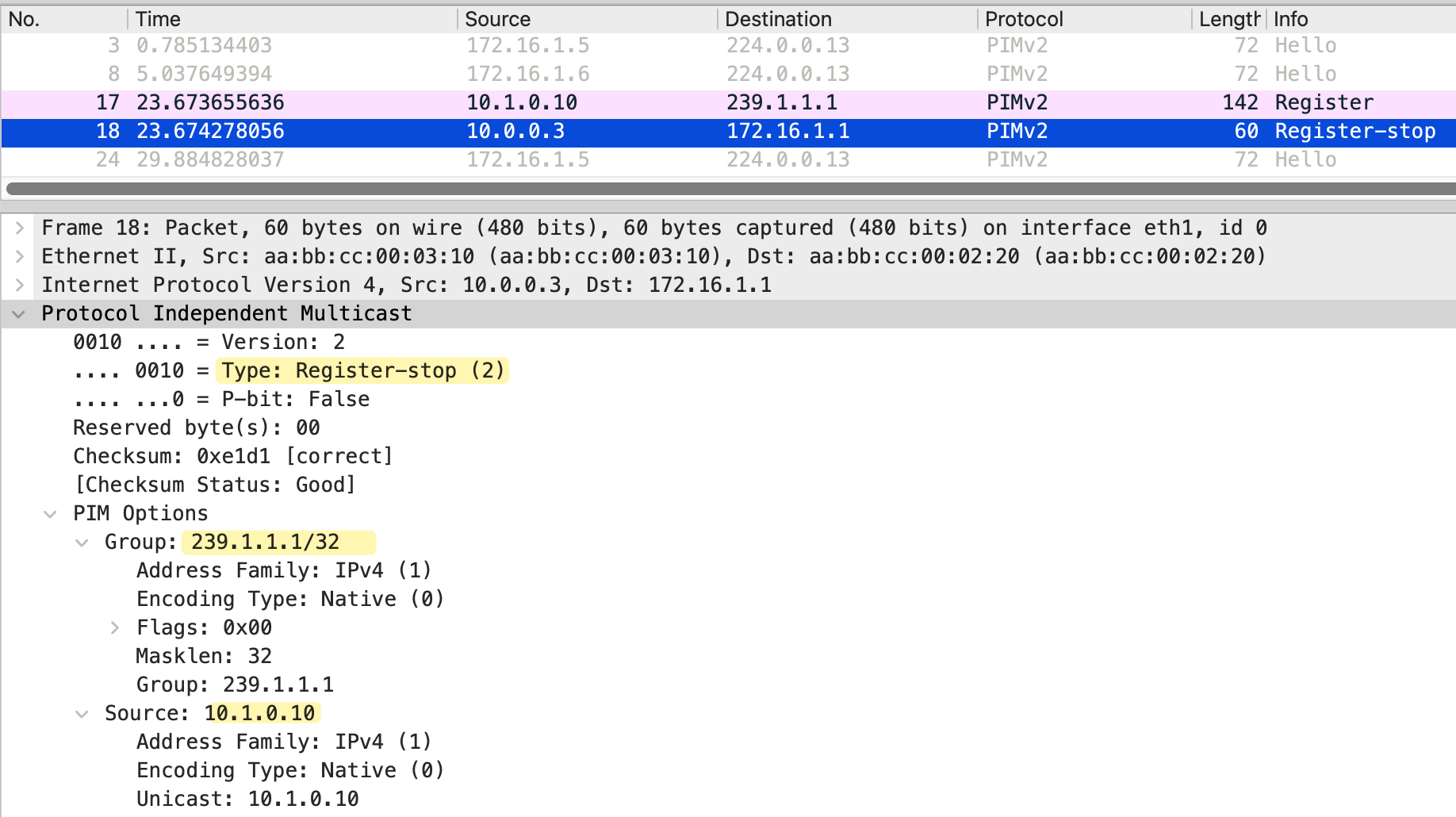
Send v2 Register-Stop to 172.16.1.1 for 10.1.0.10, group 239.1.1.1When r3, the RP, receives the Register message, it learns about the source. However, since there are no receivers joined to this group, aka no (*,G) entry on r3/RP, the RP has nowhere to forward the traffic. The RP sends a Register-Stop message back to r1, telling it to stop sending Register messages for this source and group.
In the packet capture, we can see the Register-Stop with source 10.0.0.3 and destination 172.16.1.1. The message includes the group address 239.1.1.1 and the source address 10.1.0.10.
Looking at the multicast routing table on r1, we see both a (*,G) and an (S,G) entry for 239.1.1.1. The outgoing interface list is Null for both entries, meaning traffic is not being forwarded anywhere.
- S - Sparse
- P - Pruned
- F - Register flag (we were able to register with the RP)
- T - SPT-bit set (meaning we have received some multicast packets on the S,G tree)
r1#show ip mroute
IP Multicast Routing Table

(*, 239.1.1.1), 00:00:35/stopped, RP 10.0.0.3, flags: SPF
  Incoming interface: Ethernet0/2, RPF nbr 172.16.1.2
  Outgoing interface list: Null

(10.1.0.10, 239.1.1.1), 00:00:35/00:02:24, flags: PFT
  Incoming interface: Ethernet0/1, RPF nbr 0.0.0.0
  Outgoing interface list: Null
It can be confusing to see both a (*,G) and an (S,G) entry here. This is just how Cisco displays the output. The only (at least for me) useful information we can get from the (*,G) entry is that it shows the RP address 10.0.0.3. The (S,G) entry is showing the incoming interface Ethernet0/1 where the source is connected and the RPF neighbor as 0.0.0.0 because the source is directly connected. The incoming interface for the (*,G) entry is Ethernet0/2, which is the interface toward the RP via r2.
On r3, we see similar entries with empty outgoing interface lists, confirming there are no receivers for this group.
r3#show ip mroute
IP Multicast Routing Table

(*, 239.1.1.1), 00:00:11/stopped, RP 10.0.0.3, flags: SP
  Incoming interface: Null, RPF nbr 0.0.0.0
  Outgoing interface list: Null

(10.1.0.10, 239.1.1.1), 00:00:11/00:02:48, flags: P
  Incoming interface: Ethernet0/1, RPF nbr 172.16.1.5
  Outgoing interface list: Null
In this scenario, r2 is just an innocent bystander. Even though it sits between r1 and r3, it has no idea about this multicast traffic. This is because the PIM Register message is sent as unicast directly from r1 to the RP address 10.0.0.3. The packet travels through r2 as regular unicast traffic, and r2 simply forwards it based on its unicast routing table without ever looking at the PIM or multicast content inside.
Even after receiving a Register-Stop, the FHR (r1) continues to send periodic Register messages to the RP, approximately every 120 seconds, to check if any receivers have joined. However, these subsequent Register messages are different from the initial one.
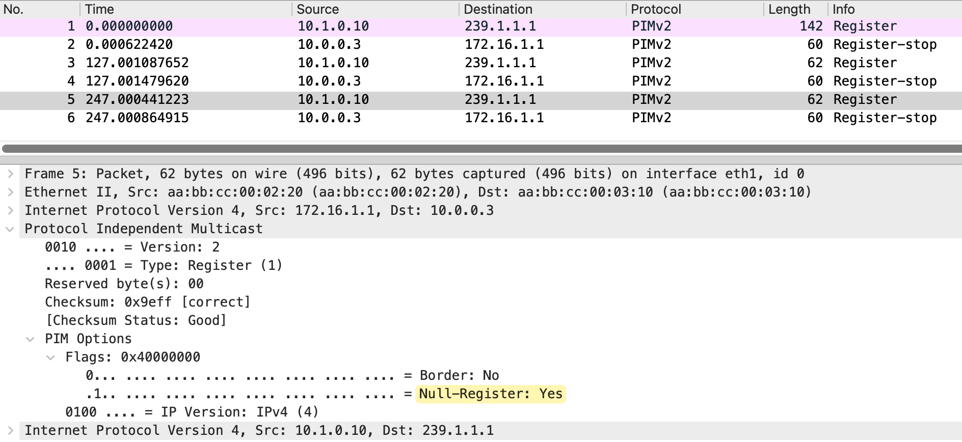
Looking at the packet capture, the first Register message at frame 1 is 142 bytes and contains the actual encapsulated multicast packet, including the ICMP payload from our ping. After the RP sends a Register-Stop, the following Register messages at frames 3 and 5 are only 62 bytes. These are called Null-Register messages. The Null-Register flag is set to Yes, indicating there is no encapsulated data inside.
The RP responds to each Null-Register with a Register-Stop since there are still no receivers. This cycle continues as long as the source keeps sending traffic.
3 - Receiver Joins First, Then Source Starts Sending
Now let's look at the scenario where a receiver joins the group first, and then the source starts sending traffic. For this example, I have disabled SPT switchover (on the LHRs) so that traffic continues to flow through the RP. By default, the last hop router would switch from the shared tree to the shortest path tree to receive traffic directly from the source. We will cover SPT switchover later in this post.
r6(config)#ip pim spt-threshold infinity
r6(config)#end
r7(config)#ip pim spt-threshold infinity
r7(config)#endAt a high level, here is what happens in this scenario. First, receiver_01 joins the multicast group 239.1.1.1. The last hop router sends a PIM Join toward the RP, building the (*,G) shared tree. At this point, the RP has a tree built toward the receiver, but no source is sending traffic yet. We already covered this in detail.

When the source starts sending traffic, the first hop router encapsulates the first multicast packet in PIM Register message and sends it to the RP. The RP decapsulates the packet and forwards it down the shared tree toward the receivers. The RP then sends a PIM Join (S,G) back toward the source, hop by hop. This Join travels from r3 to r2, and from r2 to r1. Each router along the path creates an (S,G) entry and adds the interface where the Join was received to its outgoing interface list.
r2#show ip mroute
IP Multicast Routing Table

(*, 239.1.1.1), 00:00:07/stopped, RP 10.0.0.3, flags: SP
  Incoming interface: Ethernet0/2, RPF nbr 172.16.1.6
  Outgoing interface list: Null

(10.1.0.10, 239.1.1.1), 00:00:07/00:02:52, flags: T
  Incoming interface: Ethernet0/1, RPF nbr 172.16.1.1
  Outgoing interface list:
    Ethernet0/2, Forward/Sparse, 00:00:07/00:03:24, flags:
Once the RP starts receiving native multicast traffic from the source, it sends a Register-Stop to the first hop router to stop the encapsulation. Traffic now flows natively from the source to the RP, and then down the shared tree to the receivers.
Now, to recap and looking at the diagram, the green dotted line on the right represents the shared tree, also called the RP tree, built from r3 (the RP) down through r5 and r7 to reach the receivers. This tree was created when receiver_01 joined the group and r7 sent a PIM Join toward the RP.
The orange dotted line at the top represents the source tree, also called the SPT or (S,G) tree. This path was built when the RP sent a PIM Join back toward the source after receiving the first Register message. The source tree runs from the sender through r1 and r2 to reach r3. With both trees in place, traffic flows from the sender to r1, then natively through r2 to r3 via the source tree. At r3, the traffic switches onto the shared tree and flows down through r5 and r7 to reach the receivers.
When we send a ping from the sender, notice that request 1 receives two replies from receiver_01.
sender#ping 239.1.1.1 repeat 5
Type escape sequence to abort.
Sending 5, 100-byte ICMP Echos to 239.1.1.1, timeout is 2 seconds:

Reply to request 0 from receiver_01 (10.1.1.11), 7 ms
Reply to request 1 from receiver_01 (10.1.1.11), 3 ms
Reply to request 1 from receiver_01 (10.1.1.11), 21 ms
Reply to request 2 from receiver_01 (10.1.1.11), 2 ms
Reply to request 3 from receiver_01 (10.1.1.11), 3 ms
Reply to request 4 from receiver_01 (10.1.1.11), 3 ms
Looking at the packet capture, we can see Register messages at frames 10, 13, and 16, with the RP sending a Join/Prune at frames 11 and 14, and finally a Register-Stop at frame 17.
This duplicate reply happens during the transition period. When the source first starts sending, r1 encapsulates the multicast packets in Register messages and sends them to the RP. The RP decapsulates these packets and forwards them down the shared tree to the receiver. At the same time, the RP sends a Join back toward the source to build the source tree. For a brief moment, the RP receives the same multicast packet twice, once via the Register message from r1 and once natively via the newly built source tree through r2. Both copies get forwarded down the shared tree, resulting in duplicate packets reaching the receiver. Once the RP sends the Register-Stop and r1 stops encapsulating, the duplication stops, and traffic flows only via the native path.
In all of this chaos, r4 has no idea what's happening and doesn't have the multicast state on its multicast route table. (A bit sad it got left out if you think about it 🙂)
r4#show ip mroute
IP Multicast Routing Table

 Timers: Uptime/Expires
 Interface state: Interface, Next-Hop or VCD, State/Mode
4 - Source Starts Sending First, Then Receiver Joins
Now let's look at the reverse scenario where the source starts sending traffic first, and then a receiver joins the group. This is actually simpler to understand because we have already covered both parts separately. We saw what happens when a source sends traffic with no receivers, and we saw what happens when a receiver joins with no source. In this scenario, those two processes simply happen one after the other.
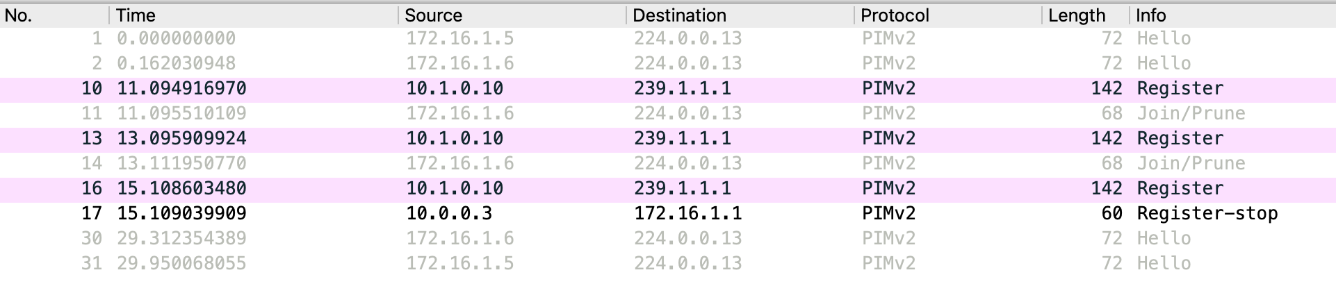
When the source starts sending traffic with no receivers, the first hop router sends PIM Register messages to the RP. The RP has no receivers, so it responds with a Register-Stop. The first hop router then periodically sends Null-Register messages to check if any receivers have joined. Here is the packet capture on r3's Et0/1 interface.
When a receiver joins later, the last hop router sends a PIM Join toward the RP. Looking at the packet capture, we can see the Join at frame 10.
As long as the multicast traffic is flowing, you will continue to see Null-Register messages from the first hop router approximately every 120 seconds. The RP responds to each one with a Register-Stop since it is already receiving native traffic through the source tree.
PIM SPT Switchover
So far, we have seen traffic flowing from the source to the RP via the source tree, and then from the RP down to the receivers via the shared tree. This works, but it is not always the most efficient path. The traffic has to go through the RP even if there is a shorter path directly from the source to the receiver.
SPT switchover allows the last hop router to switch from the shared tree to the shortest path tree. Instead of receiving traffic via the RP, the last hop router builds a direct path back to the source. This creates a more optimal route for the multicast traffic, bypassing the RP entirely. By default, on Cisco/Juniper devices, SPT switchover happens as soon as the first packet arrives via the shared tree. The last hop router immediately sends an (S,G) Join toward the source to build the shortest path tree. Once traffic starts arriving via the SPT, the last hop router prunes itself off the shared tree for that specific source.
Remember in the previous section, we disabled SPT switchover to keep things simple. Now we enable it back on both r6 and r7, which is the default behaviour on Cisco devices.
! r6 and r7

r(config)#ip pim spt-threshold ?
  0         Always switch to source-tree
  infinity  Never switch to source-tree

r(config)#ip pim spt-threshold 0
r(config)#
The first diagram shows the initial state. The first packet travels from the source through r1 and r2 to the RP (r3) via the source tree.
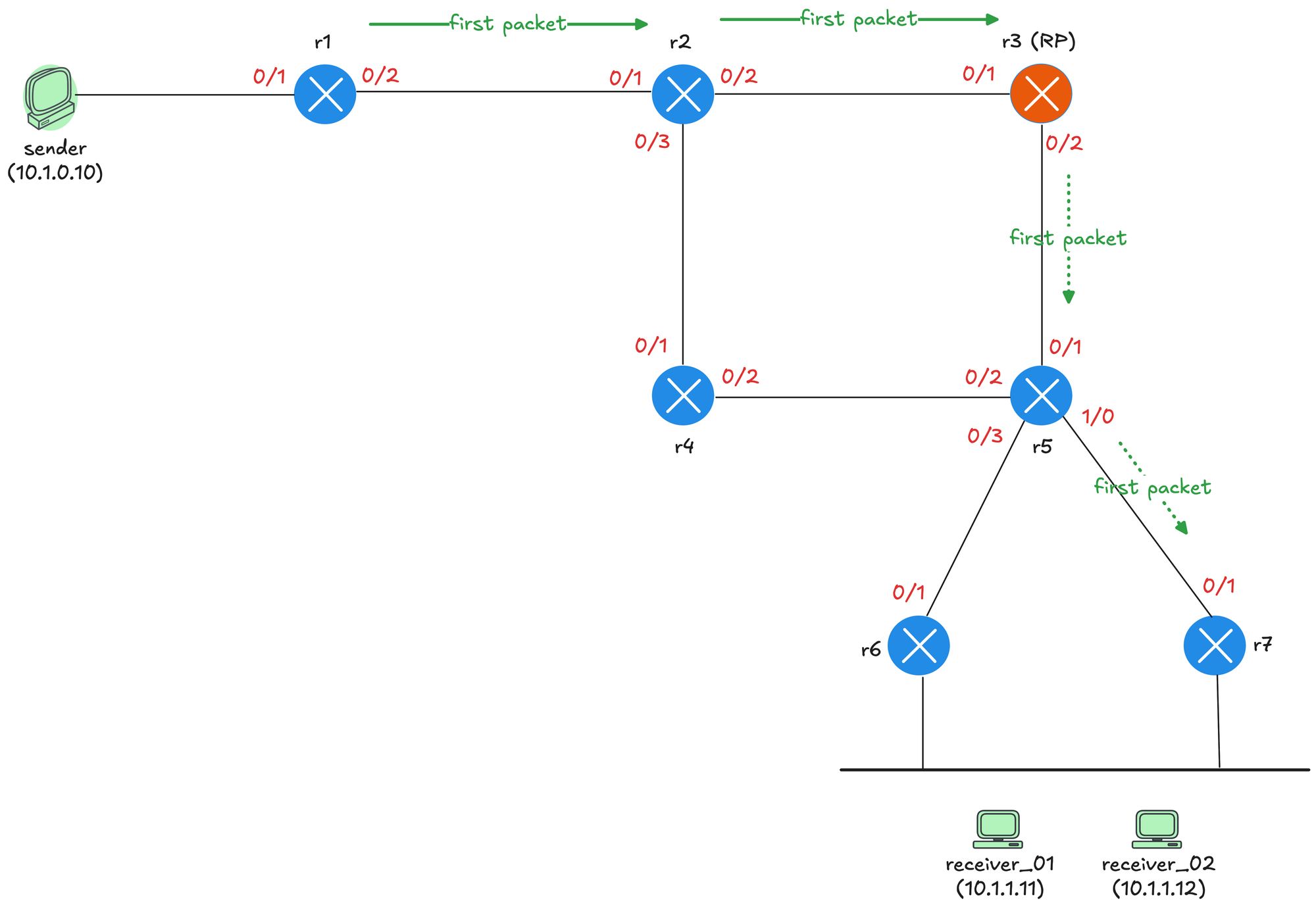
The RP then forwards it down the shared tree through r5 to r7, which delivers it to the receiver. At this point, r7 receives the first multicast packet and learns the source IP address.
The second diagram shows what happens next. As soon as r7 receives the first packet, it knows the source address and sends an (S,G) Join toward the source.
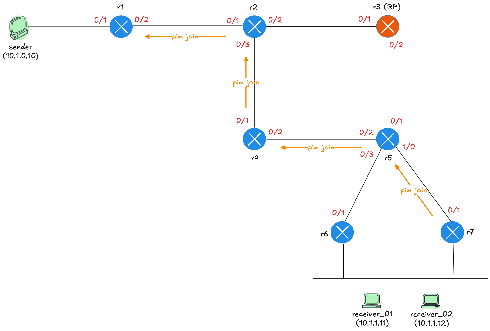
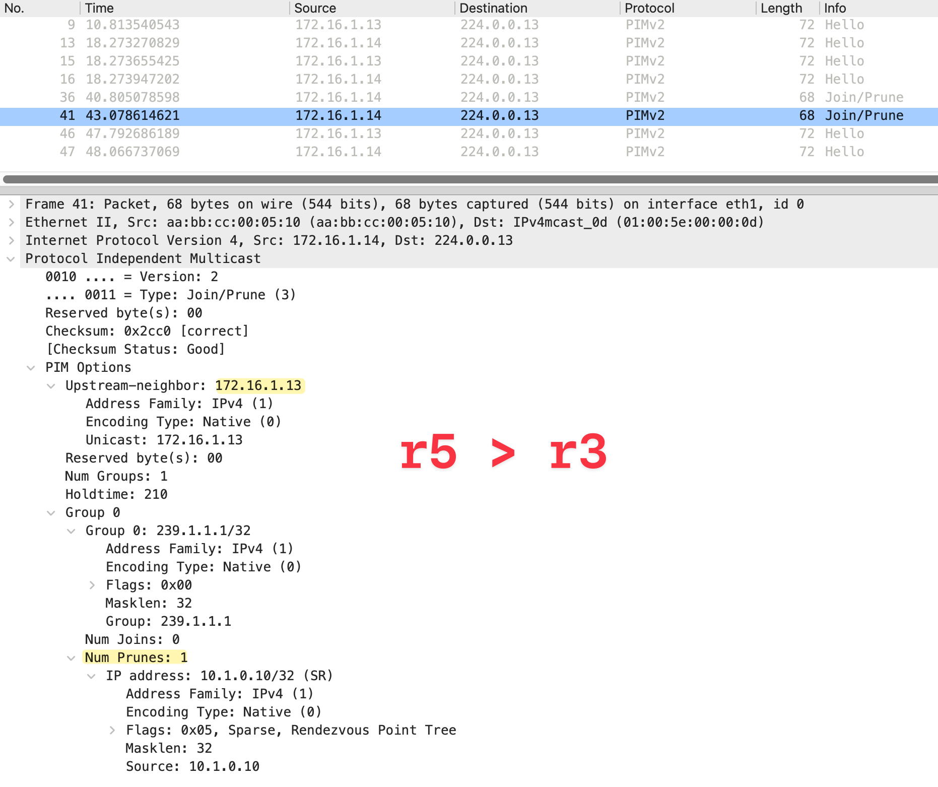
The Join travels from r7 to r5. At r5, there are two equal cost paths to reach the source, one via r4 and one via r3 (the RP). Both paths were learned via OSPF.
r5#show ip route 10.1.0.10
Routing entry for 10.1.0.0/24
  Known via "ospf 1", distance 110, metric 40, type intra area
  Last update from 172.16.1.17 on Ethernet0/2, 00:03:35 ago
  Routing Descriptor Blocks:
    172.16.1.17, from 10.0.0.1, 00:03:35 ago, via Ethernet0/2
      Route metric is 40, traffic share count is 1
  * 172.16.1.13, from 10.0.0.1, 00:03:35 ago, via Ethernet0/1
      Route metric is 40, traffic share count is 1
When there are equal cost paths, the RPF interface is determined by the next-hop with the higher IP address. In this case, r4 wins because its IP address 172.16.1.17 is higher than r3's 172.16.1.13. So the Join continues from r5 to r4, then to r2, and finally to r1.
r5#show ip rpf 10.1.0.10
RPF information for sender (10.1.0.10)
  RPF interface: Ethernet0/2
  RPF neighbor: r4 (172.16.1.17)
  RPF route/mask: 10.1.0.0/24
  RPF type: unicast (ospf 1)
  Doing distance-preferred lookups across tables
  RPF topology: ipv4 multicast base, originated from ipv4 unicast base
The third diagram shows the final state after SPT switchover completes. Traffic now flows directly from the source through r1, r2, r4, r5, and r7 to the receiver, completely bypassing the RP.
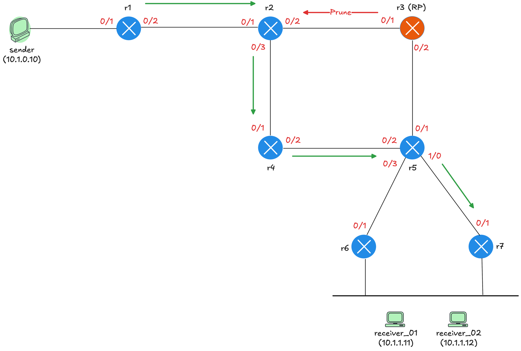
When r5 starts receiving traffic from r4 via the (S,G) tree, it sends a Prune toward r3 on the shared tree since it no longer needs traffic via that path. The RP also sends a Prune toward r2 since it no longer has any downstream receivers.
We can now see an (S,G) entry on r7, which we did not have in the earlier sections when traffic was flowing only via the shared tree.
r7#show ip mroute
IP Multicast Routing Table

(*, 239.1.1.1), 00:04:00/stopped, RP 10.0.0.3, flags: SJC
  Incoming interface: Ethernet0/1, RPF nbr 172.16.1.25
  Outgoing interface list:
    Ethernet0/2, Forward/Sparse, 00:04:00/00:02:53, flags:

(10.1.0.10, 239.1.1.1), 00:04:00/00:02:46, flags: JT
  Incoming interface: Ethernet0/1, RPF nbr 172.16.1.25
  Outgoing interface list:
    Ethernet0/2, Forward/Sparse, 00:04:00/00:02:53, flags:
References
I learnt a lot about PIM Sparse Mode through this video and used a similar lab topology, so credit to the author for making such a great deep dive video.