
Packet capture is very useful when you troubleshoot network connectivity issues or monitor suspicious activity.
Diagram
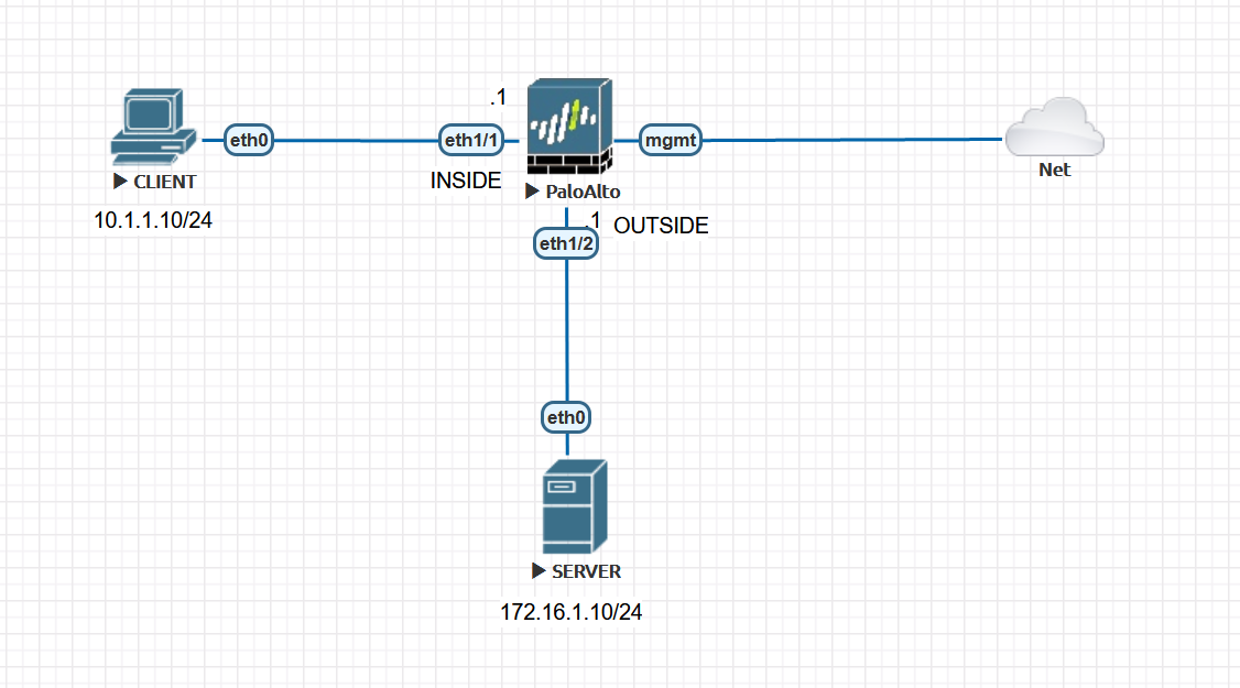
Few things to consider
- Four packet capture filters can be added with a variety of attributes.
- Packet captures are session/flow based, so having a single filter is enough for capturing both inbound and outbound traffic.
Packet Capture Stages
There are four stages:
- drop - where packets get discarded. Example, security polciy denying the traffic
- firewall - captures packets in the firewall stage.
- receive - captures the packets as they ingress the firewall interface before they go into the firewall engine (pre-NAT)
- transmit - captures packets as they egress out of the firewall engine (post-NAT)
Example 1 - Packet Capture without NAT
Initiate a ping from CLIENT to the SERVER and capture both ICMP echo request and ICMP echo reply.
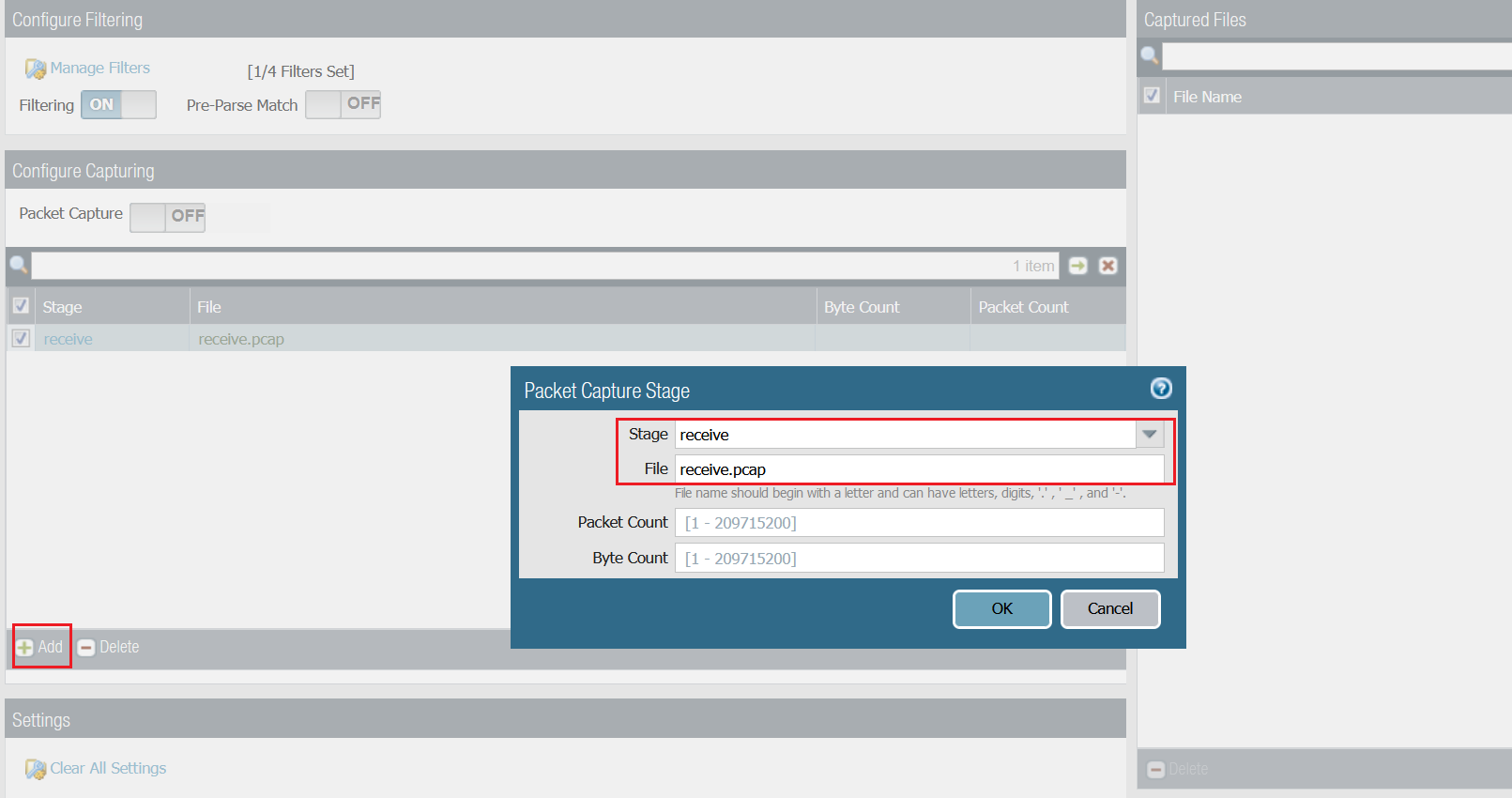
You can configure packet capture by going to Monitor > Packet Capture
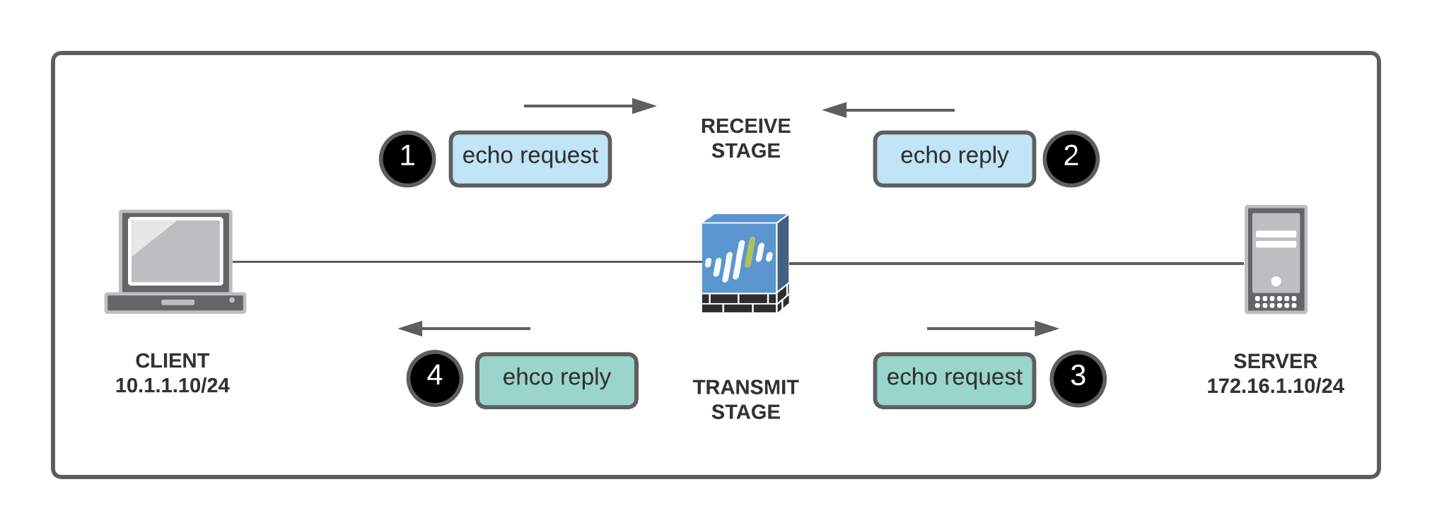
- Packets 1 & 2 are ingressing the firewall
- Packets 3 & 4 are egressing the firewall
- Packets 1 & 3 are the same
- Packets 2 & 4 are the same
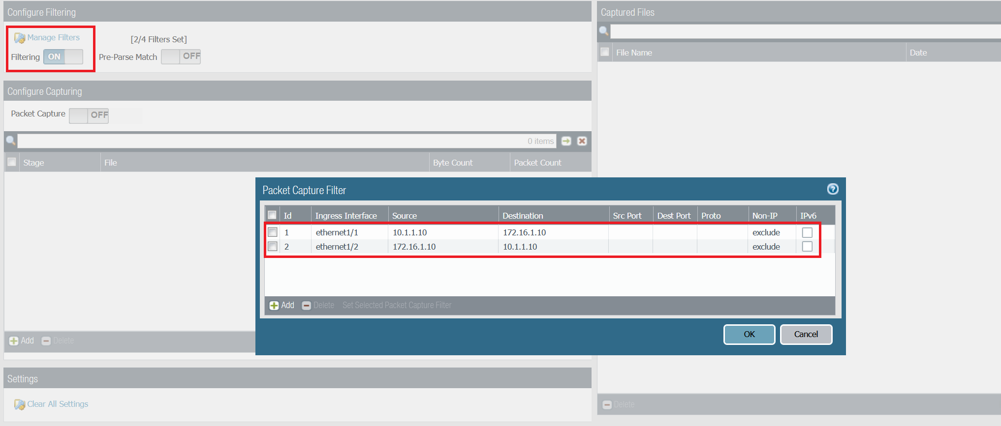
Step 1 - Configure capture filters
The filter shown below captures both echo request and echo reply on both receive and transmit stage. For this example, one stage (receive) is more than enough.
- receive stage - packets 1 & 2 (shown on the example below)
- transmit stage - packets 3 & 4
If you only configure filter Id-1 then the receive stage will capture packet #1 and the transmit stage will capture packet#4. You will then need to merge both capture files to have the full picture.
Step 2 - Configure receive stage
Step 3 - Initiate some traffic and download the capture file
CLIENT> ping 172.16.1.10

172.16.1.10 icmp_seq=1 timeout
84 bytes from 172.16.1.10 icmp_seq=2 ttl=63 time=4.393 ms
84 bytes from 172.16.1.10 icmp_seq=3 ttl=63 time=1.809 ms
84 bytes from 172.16.1.10 icmp_seq=4 ttl=63 time=1.618 ms
84 bytes from 172.16.1.10 icmp_seq=5 ttl=63 time=1.184 ms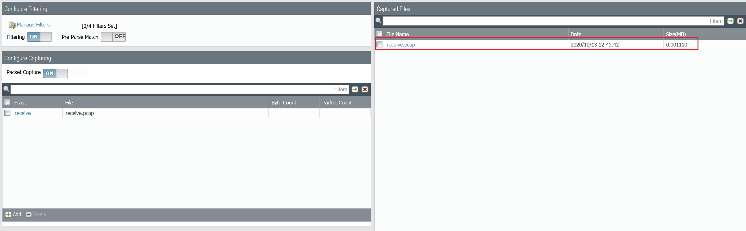
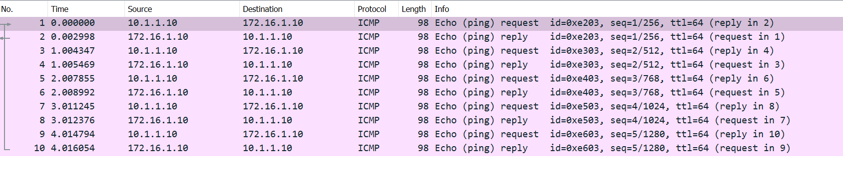
As you can see above, both echo requests and echo replies are captured on the receive stage.
Example 2 - Packet Capture with NAT
Diagram
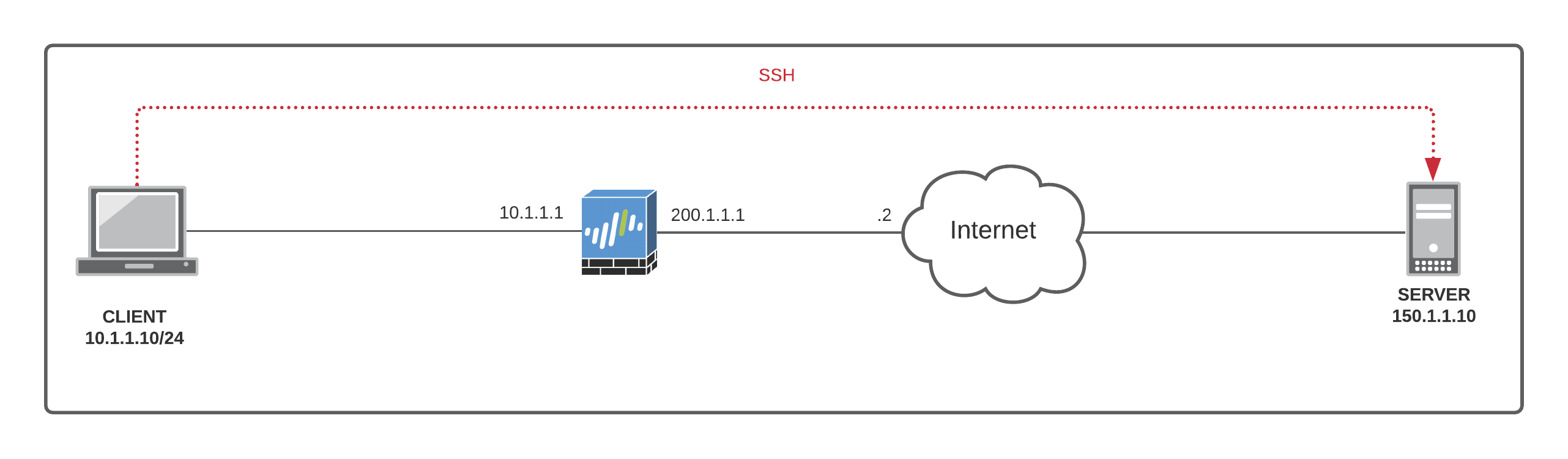
I configured a SOURCE NAT policy which translates the source IP of the client to the Palo Alto interface public routable IP of 200.1.1.1 when going out to the Internet.
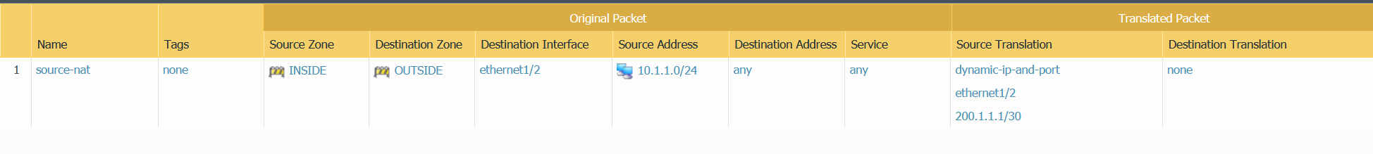
Let's initiate an SSH connection from the CLIENT to the SERVER. When the traffic leaves the Firewall (post-NAT), the source IP of the SSH traffic will be 200.1.1.1
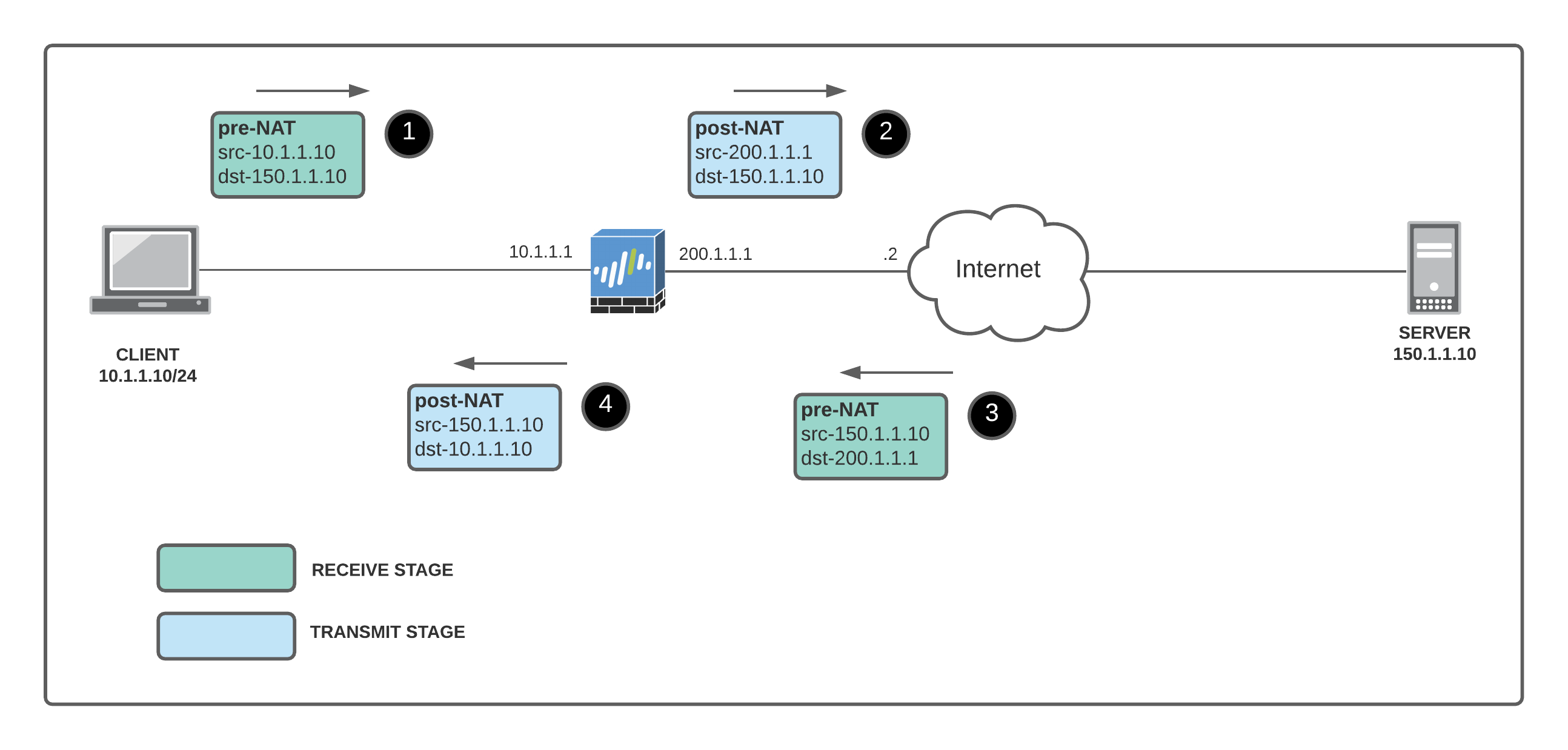
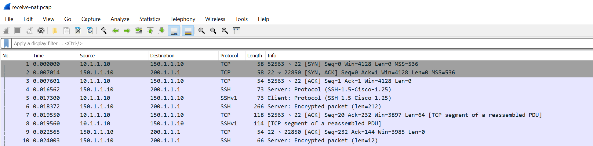
- The receive stage has the client private IP to the server public IP #1, and the return packet from the server public IP to the firewall external IP #3 (receive stage is pre-NAT)
- The transmit stage has the firewall external IP (source NAT) to the server public IP #2, and the return packet from the server public IP to the client private IP #4.
Let's configure the firewall for packet capture.
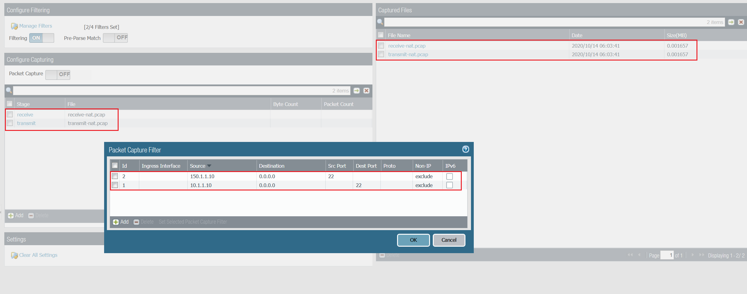
You can use both receive and transmit stage capture files for troubleshooting or NAT verification. You can change and tweak the capture filters to suite your needs.
Reference
Thanks for reading.
As always, your feedback and comments are more than welcome.