
What if I tell you that configuring site-to-site VPN on Palo Alto firewalls is easier than you may think? Just like any other VPN, you will have to define phase-1 and phase-2 profiles that match the other side, define pre-shared keys and finally set up the tunnel interfaces.
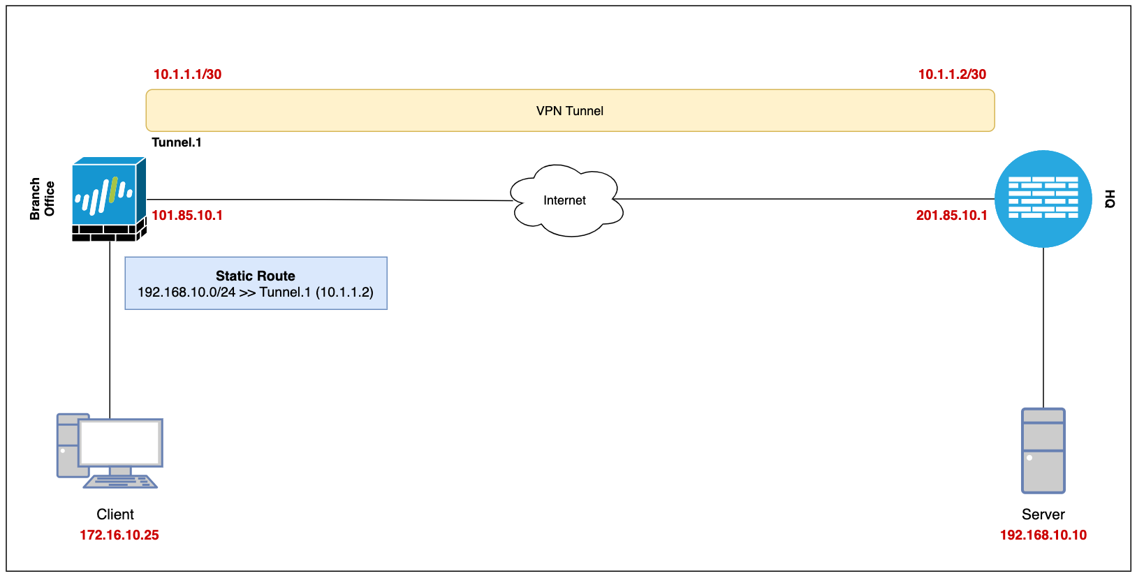
Our ultimate goal is to set up a site-to-site VPN between the Branch Office (Palo Alto) and the Headquarters (which can be any firewall) and enable connectivity so, the devices in either location can access each other via a secure channel.
Let's assume the client-pc (172.16.10.25) in the branch office needs to access a web server (192.168.10.10) in the headquarter and we need to set up a VPN tunnel to provide connectivity.
This blog post assumes prior knowledge of Palo Alto firewalls and site-to-site VPN fundamentals.
Diagram
Configuration
Security Zone, Route and Tunnel Interface
To set up a VPN tunnel, the Layer 3 interface at each end must have a logical tunnel interface for the VPN peers to connect to and establish a VPN tunnel.
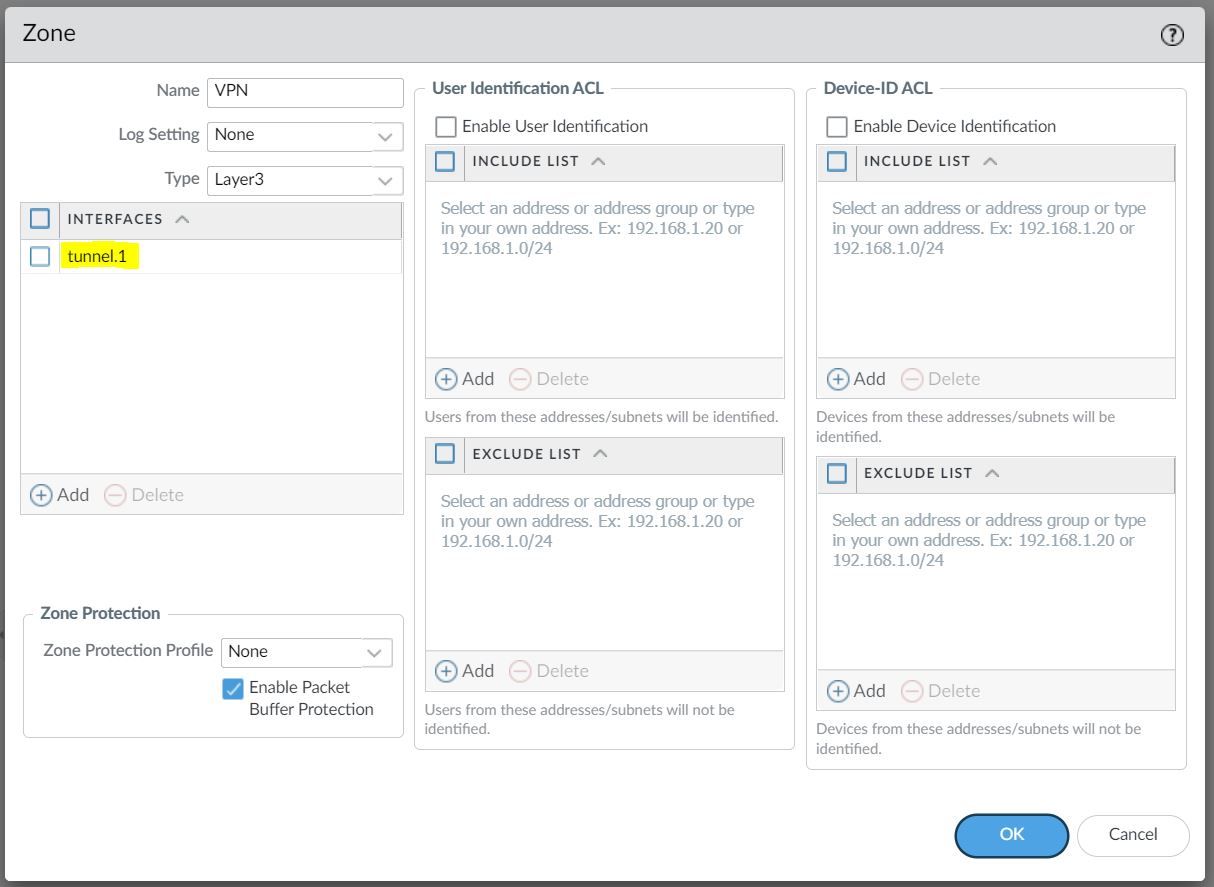
The tunnel interface must belong to a Security Zone to apply policies and it must be assigned to a virtual router.
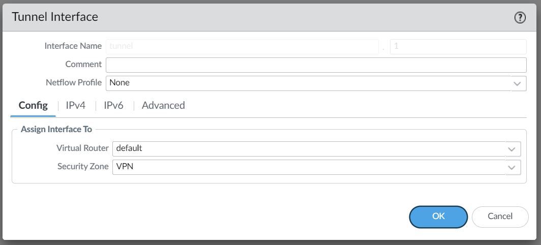
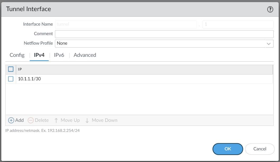
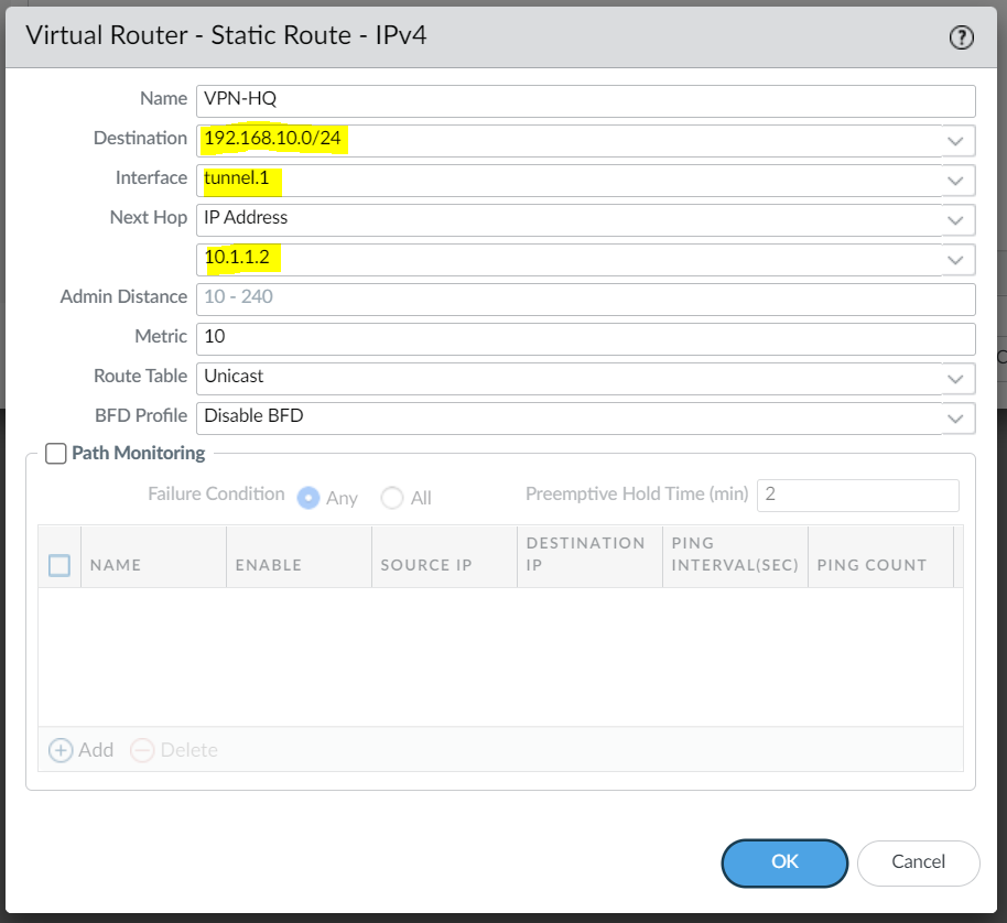
For this example, I'm creating a Tunnel interface tunnel.1 and assigned an IP of 10.1.1.1/30. The VPN peer will also have a Tunnel with the IP of 10.1.1.2/30 (not shown in this example)
The Tunnel interface is then assigned to a Security Zone called VPN, the name can be anything and you can add multiple interfaces to the same zone depending on how you want to manage the Security Policies among multiple VPNs. You can also use an existing zone if you want to.
You will also need a static route (or dynamic routing protocols) that points to the Tunnel interface as the next-hop to reach the destination subnet.
Phase 1 / IKE Crypto Profile
In Phase 1, the VPN peers use the parameters defined in the IKE Gateway (more on this later) and the IKE Crypto profile to authenticate each other and set up a secure control channel.
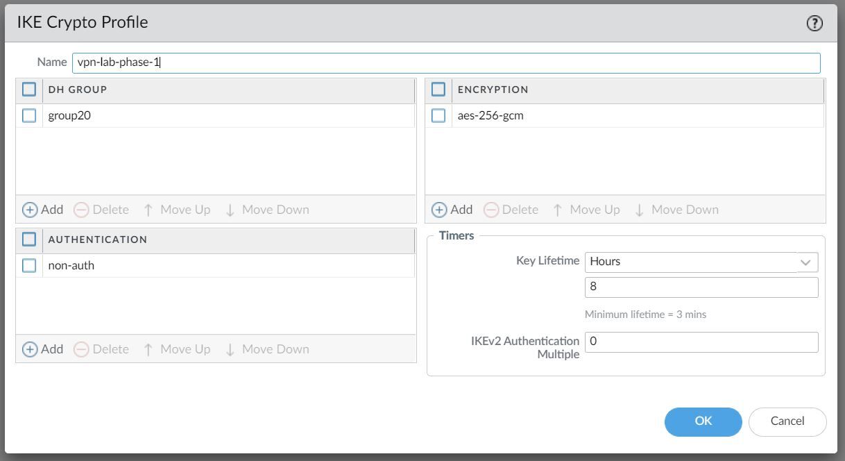
The IKE Crypto Profile is used to set up the encryption and authentication algorithms used for the initial key exchange process, and the lifetime of the keys. At a later stage, we will need to attach the profile to the IKE Gateway for the configuration to take effect.
To begin defining the Phase 1 configuration, navigate to Networks> IKE Crypto and Add a new Profile.
Ideally, you want to use the strongest authentication and encryption algorithms the peer can support. For authentication, you can use SHA-256 or higher. SHA-1 or MD5 are considered weak and not recommended to use in a production environment.
For the encryption algorithm, you can use AES. DES and 3DES are considered weak and vulnerable. AES-GCM provides the strongest security and has built-in authentication, so you must set Authentication to none if you select aes-256-gcm or aes-128-gcm encryption.
Phase 2 / IPSec Crypto Profile
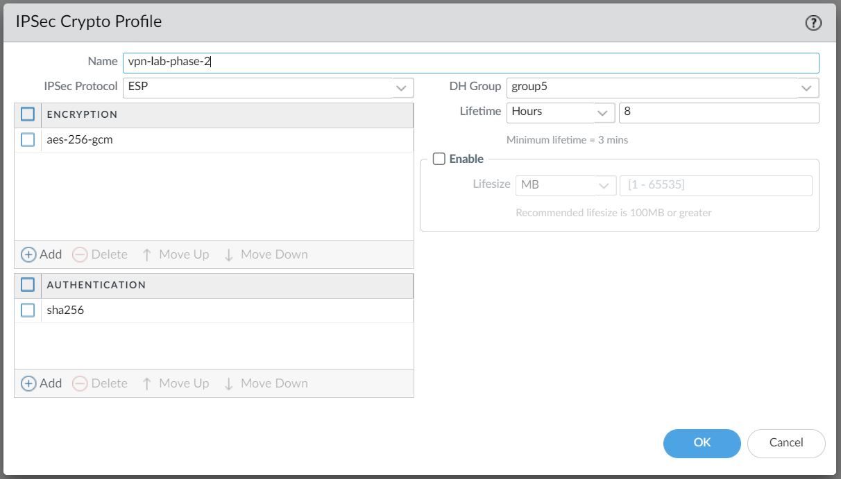
In Phase 2 the channel is further secured for the transfer of data between the networks. You can use either ESP (Encapsulating Security Payload) or AH (Authentication Header) to enable secure communication. ESP allows you to encrypt the entire IP packet whereas AH does not encrypt the data payload and is unsuitable if your deployment requires privacy.
For this example, I've chosen to use AES-256-GCM for encryption and SHA-256 for Authentication.
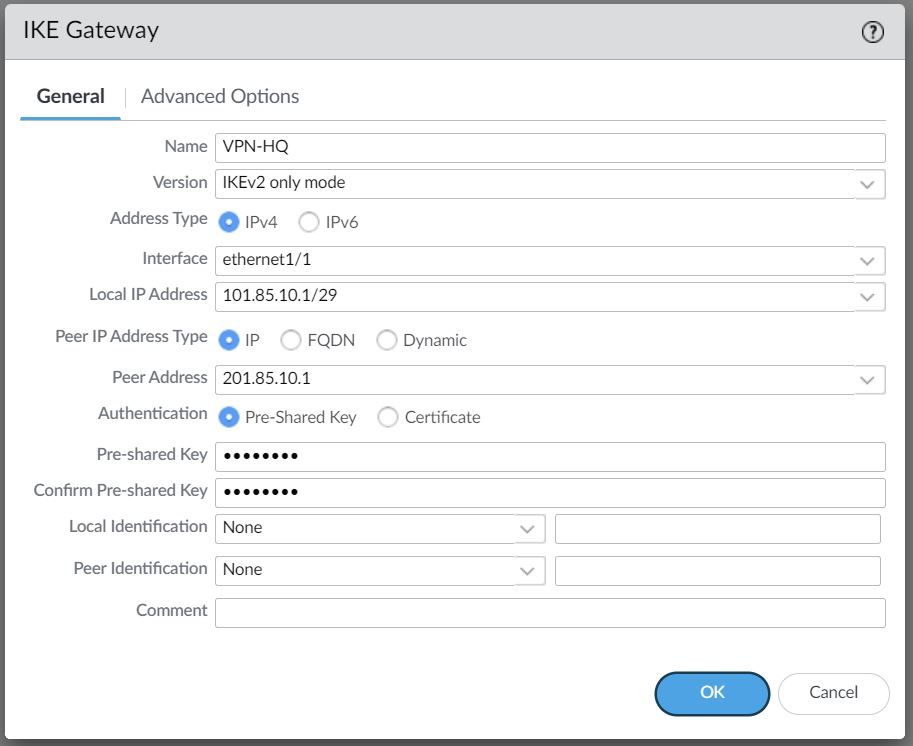
IKE Gateway
Firewalls that initiate and terminate VPN connections across the two networks are called the IKE Gateways.
To set up the VPN tunnel and send traffic between the IKE Gateways, each peer must have an IP address, of course (static/dynamic). The VPN peers can also use pre-shared keys or certificates to mutually authenticate each other. The following example uses pre-shared keys (PSK). You can also choose between IKEv1 and IKEv2 depending on your requirement.
The interface selected should be the interface that connects to your ISP.
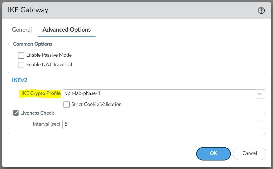
Under the advanced settings, please select the IKE Crypto Profile we created earlier.
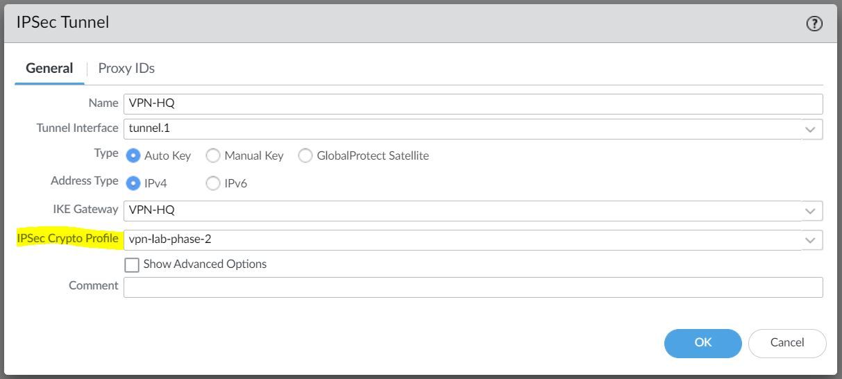
IPSec Tunnel
The final step is to create an IPSec tunnel and attach the IPsec Crypto Profile we created earlier.
Any traffic that gets sent out to the Tunnel interface is encrypted and sent out to the peer via the tunnel.
Verification
Once the configuration has been completed, I'm going to send ICMP echo (ping) traffic from the Client to the server to verify that the tunnel is working.
client-pc> ping 192.168.10.10
84 bytes from 192.168.10.10 icmp_seq=1 ttl=63 time=7.117 ms
84 bytes from 192.168.10.10 icmp_seq=2 ttl=63 time=2.062 ms
84 bytes from 192.168.10.10 icmp_seq=3 ttl=63 time=2.397 ms
84 bytes from 192.168.10.10 icmp_seq=4 ttl=63 time=2.204 ms
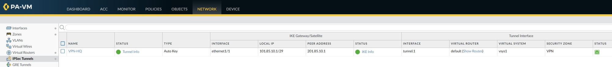
84 bytes from 192.168.10.10 icmp_seq=5 ttl=63 time=2.196 msIPSec Tunnel - As you can see below, the IPSec tunnel status is turned green which means the tunnel is up and running.
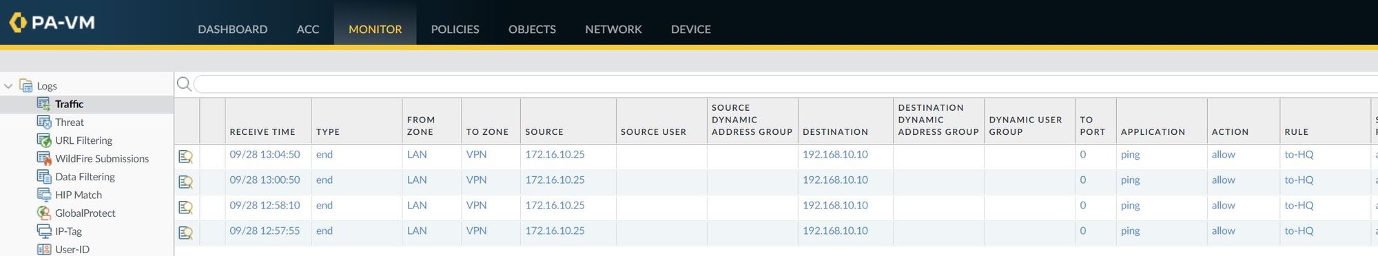
I've also attached a screenshot of the traffic logs that shows the traffic from the client to the server.
Troubleshooting
You can also use CLI commands to verify the VPN status and two of the commands I regularly use are show vpn ike-sa gateway and show vpn ipsec-sa
admin@PA-VM> show vpn ike-sa gateway
  VPN-HQ   VPN-HQ
  <value>  Show for given IKE gateway

admin@PA-VM> show vpn ike-sa gateway VPN-HQ

There is no IKEv1 phase-1 SA found.

There is no IKEv1 phase-2 SA found.


IKEv2 SAs
Gateway ID      Peer-Address           Gateway Name                                                    Role SN       Algorithm             Established     Expiration      Xt Child  ST
----------      ------------           ------------                                                    ---- --       ---------             -----------     ----------      -- -----  --
1               201.85.10.1            VPN-HQ                                                          Resp 40       PSK/ DH5/AES256-GCM16 Sep.28 19:47:31 Sep.29 03:47:31 0  1      Established

IKEv2 IPSec Child SAs
Gateway Name                                                    TnID     Tunnel                                                          ID       Parent   Role SPI(in)  SPI(out) MsgID    ST
-------  -------- -----    --
VPN-HQ                                                          1        VPN-HQ                                                          4074     40       Resp 8F19DF40 31F33EFE 00000001 Mature

Show IKEv2 SA: Total 1 gateways found. 1 ike sa found.
admin@PA-VM> show vpn ipsec-sa
GwID/client IP TnID Peer-Address Tunnel(Gateway) Algorithm SPI(in) SPI(out) life(Sec/KB) remain-time(Sec)
-------------- ---- ------------ --------------- --------- ------- -------- ------------ ----------------
1 1 201.85.10.1 VPN-HQ(VPN-HQ) ESP/G256/ D6899B03 1BF46826 28800/Unlimited 28517
Show IPSec SA: Total 1 tunnels found. 1 ipsec sa found.You can also use show vpn flow name CLI command to verify if the firewall is passing the traffic in both directions. As you can see below, both encap and decap packets have a counter with 25 as the value.
admin@PA-VM> show vpn flow name VPN-HQ | match packets
          monitor packets seen: 0
          monitor packets reply:0
        replay packets:         0
        packets received
        encap packets:          25
        decap packets:          25
If I go ahead and send some more ping packets, the counter should increase. Let's send 5 ICMP packets and the counter should increase to 30.
client-pc> ping 192.168.10.10

84 bytes from 192.168.10.10 icmp_seq=1 ttl=63 time=4.411 ms
84 bytes from 192.168.10.10 icmp_seq=2 ttl=63 time=2.061 ms
84 bytes from 192.168.10.10 icmp_seq=3 ttl=63 time=2.192 ms
84 bytes from 192.168.10.10 icmp_seq=4 ttl=63 time=1.895 ms
84 bytes from 192.168.10.10 icmp_seq=5 ttl=63 time=2.209 ms
admin@PA-VM> show vpn flow name VPN-HQ | match packets
monitor packets seen: 0
monitor packets reply:0
replay packets: 0
packets received
encap packets: 30
decap packets: 30If the encapsulation counter is increasing and decapsulation is constant, then the firewall is sending but not receiving packets.
If the decapsulation counter is increasing and encapsulation is constant, then the firewall is receiving but not transmitting packets.