

What if I tell you that configuring a site-to-site VPN between Palo Alto and ASA is easier than you may think? Just like any other VPN, you will have to define phase-1 and phase-2 profiles that match the other side, define pre-shared keys and finally set up the tunnel interfaces to complete the configuration.
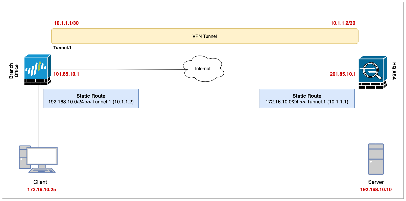
Our ultimate goal is to set up a site-to-site VPN between the Branch Office (Palo Alto) and the Headquarters (ASA) and enable connectivity so, the devices in either location can access each other via a secure channel.
Let's assume the client-pc (172.16.10.25) in the branch office needs to access a web server (192.168.10.10) in the headquarter and we need to set up a VPN tunnel to provide connectivity.
This blog post assumes prior knowledge of Palo Alto, ASA firewalls and site-to-site VPN fundamentals.
Diagram
Palo Alto Configuration
Security Zone, Route and Tunnel Interface
To set up a VPN tunnel, the Layer 3 interface at each end must have a logical tunnel interface for the VPN peers to connect to and establish a VPN tunnel.
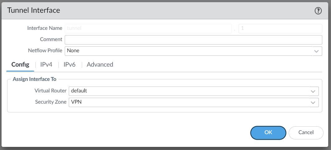
The tunnel interface must belong to a Security Zone to apply policies and it must be assigned to a virtual router.
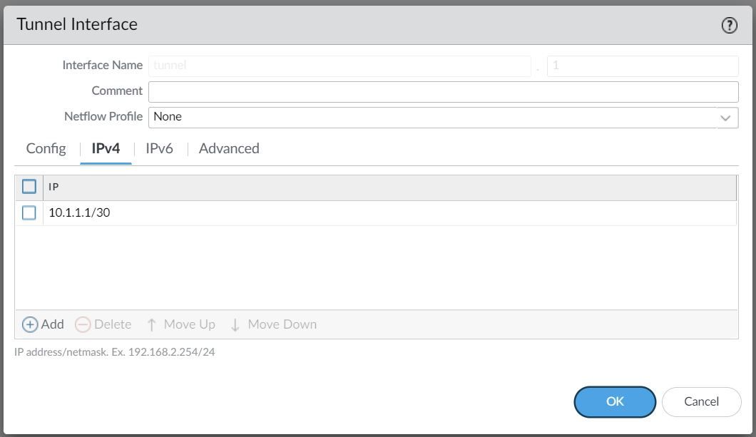
For this example, I'm creating a Tunnel interface tunnel.1 and assigning an IP of 10.1.1.1/30. The VPN peer will also have a Tunnel with the IP of 10.1.1.2/30 (not shown in this example)
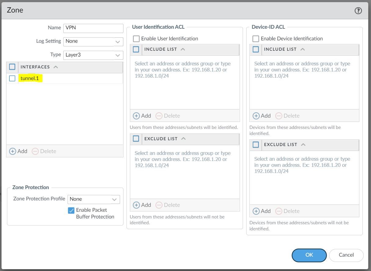
The Tunnel interface is then assigned to a Security Zone called VPN, the name can be anything and you can add multiple interfaces to the same zone depending on how you want to manage the Security Policies among multiple VPNs. You can also use an existing zone if you want to.
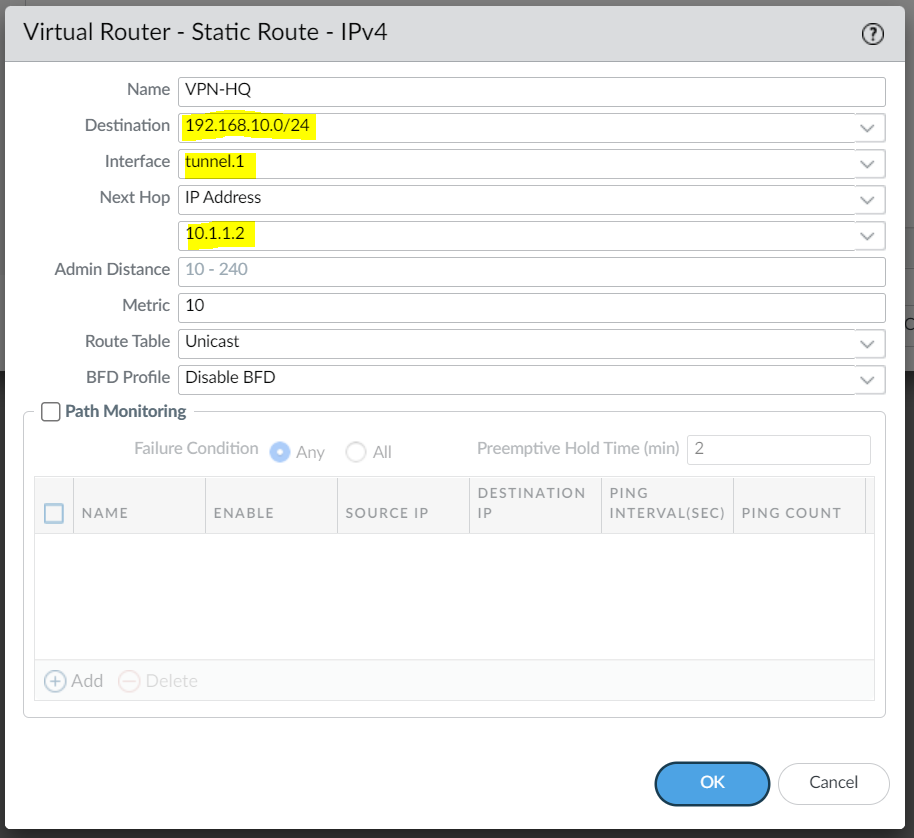
You will also need a static route (or dynamic routing protocols) that points to the Tunnel interface as the next-hop to reach the destination subnet.
Phase 1 / IKE Crypto Profile
In Phase 1, the VPN peers use the parameters defined in the IKE Gateway (more on this later) and the IKE Crypto profile to authenticate each other and set up a secure control channel.
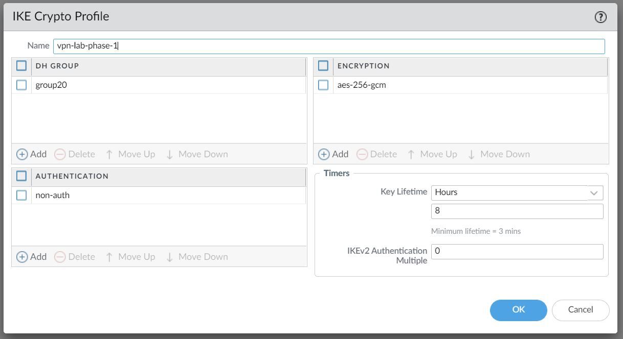
The IKE Crypto Profile is used to set up the encryption and authentication algorithms used for the initial key exchange process, and the lifetime of the keys. At a later stage, we will need to attach the profile to the IKE Gateway for the configuration to take effect.
To begin defining the Phase 1 configuration, navigate to Networks> IKE Crypto and Add a new Profile.
Ideally, you want to use the strongest authentication and encryption algorithms the peer can support. For authentication, you can use SHA-256 or higher.
For the encryption algorithm AES-GCM provides the strongest security and has built-in authentication, so you must set Authentication to none if you select aes-256-gcm or aes-128-gcm encryption.
Phase 2 / IPSec Crypto Profile
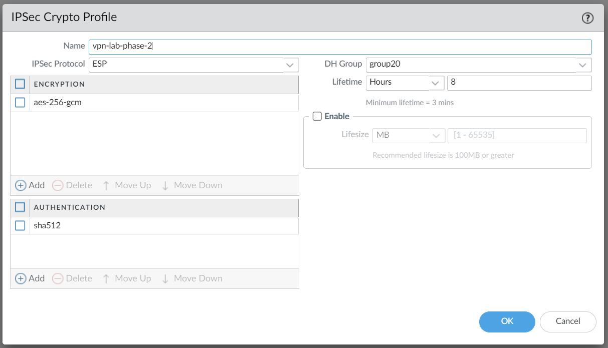
In Phase 2 the channel is further secured for the transfer of data between the networks. You can use either ESP (Encapsulating Security Payload) or AH (Authentication Header) to enable secure communication. ESP allows you to encrypt the entire IP packet whereas AH does not encrypt the data payload and is unsuitable if your deployment requires privacy.
For this example, I've chosen to use AES-256-GCM for encryption and SHA-512 for Authentication.
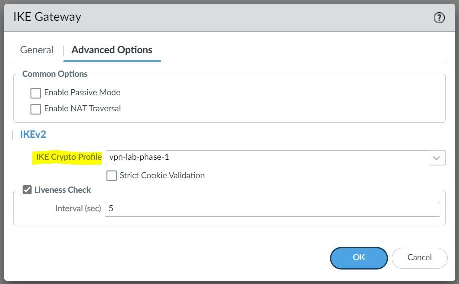
IKE Gateway
Firewalls that initiate and terminate VPN connections across the two networks are called the IKE Gateways.
To set up the VPN tunnel and send traffic between the IKE Gateways, each peer must have an IP address, of course (static/dynamic). The VPN peers can also use pre-shared keys or certificates to mutually authenticate each other. The following example uses pre-shared keys (PSK). You can also choose between IKEv1 and IKEv2 depending on your requirement.
The interface selected should be the interface that connects to your ISP.
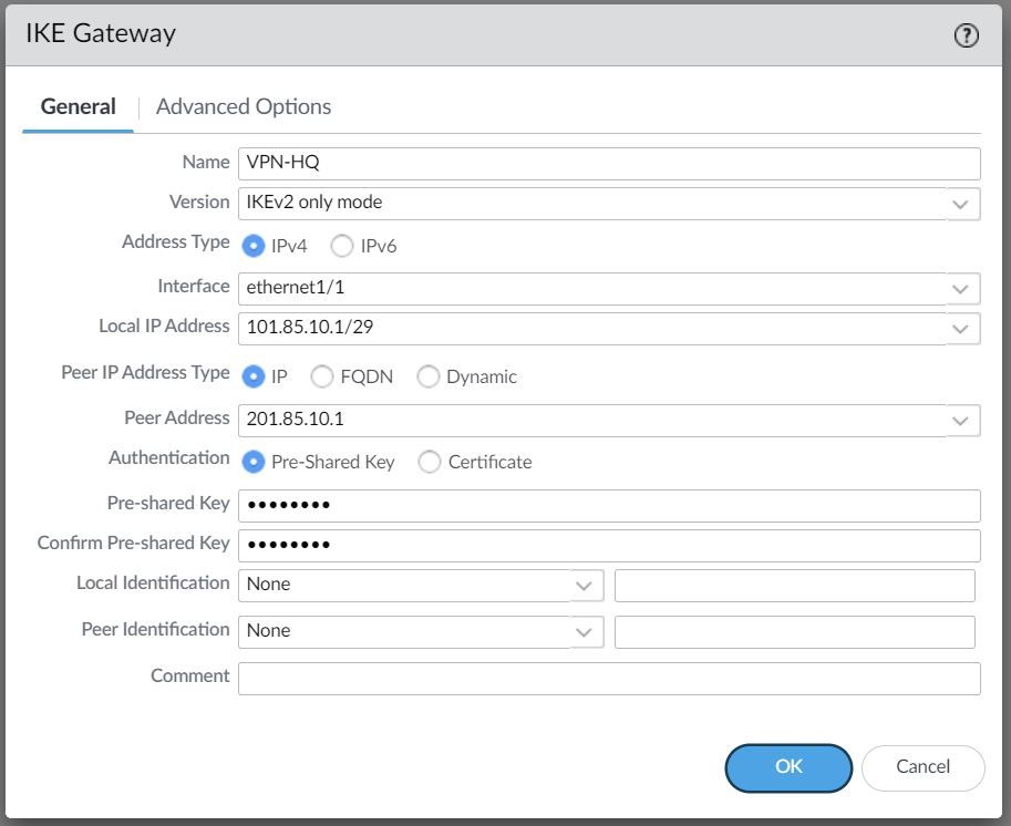
Under the advanced settings, please select the IKE Crypto Profile we created earlier.
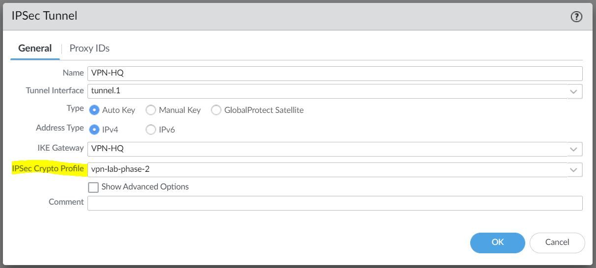
IPSec Tunnel
The final step is to create an IPSec tunnel and attach the IPsec Crypto Profile we created earlier.
Any traffic that gets sent out to the Tunnel interface is encrypted and sent out to the peer via the tunnel.
Cisco ASA
We just need to configure the matching parameters on the ASA side as shown below. I've also included the interface configurations for reference.
Interfaces
interface GigabitEthernet0/0
 nameif WAN
 security-level 0
 ip address 201.85.10.1 255.255.255.248 standby 201.85.10.2
!
interface GigabitEthernet0/1
 nameif INSIDE
 security-level 100
 ip address 192.168.10.1 255.255.255.0 standby 192.168.10.2
Enable IKEv2
Let's enable IKEv2 on the WAN interface.
crypto ikev2 enable WANPhase-1
crypto ikev2 policy 50
 encryption aes-gcm-256
 integrity null
 group 20
 prf sha384
 lifetime seconds 28800
Phase-2
crypto ipsec ikev2 ipsec-proposal VPN-LAB
 protocol esp encryption aes-gcm-256 aes-256
 protocol esp integrity sha-512

crypto ipsec profile VPN-LAB-PROFILE
 set ikev2 ipsec-proposal VPN-LAB
Tunnel Interface and Static Route
interface Tunnel1
 nameif VPN-BRANCH
 ip address 10.1.1.2 255.255.255.252
 tunnel source interface WAN
 tunnel destination 101.85.10.1
 tunnel mode ipsec ipv4
 tunnel protection ipsec profile VPN-LAB-PROFILE
route VPN-BRANCH 172.16.10.0 255.255.255.0 10.1.1.1 1Group Policy and Tunnel Groups
group-policy VPN-LAB-GP internal
group-policy VPN-LAB-GP attributes
 vpn-tunnel-protocol ikev2

tunnel-group 101.85.10.1 type ipsec-l2l
tunnel-group 101.85.10.1 general-attributes
 default-group-policy VPN-LAB-GP

tunnel-group 101.85.10.1 ipsec-attributes
 ikev2 remote-authentication pre-shared-key Cisco123
 ikev2 local-authentication pre-shared-key Cisco123
Verification
Let's send some traffic from the Client to the server to verify that the tunnel is working.
client-pc> ping 192.168.10.10

84 bytes from 192.168.10.10 icmp_seq=1 ttl=63 time=7.117 ms
84 bytes from 192.168.10.10 icmp_seq=2 ttl=63 time=2.062 ms
84 bytes from 192.168.10.10 icmp_seq=3 ttl=63 time=2.397 ms
84 bytes from 192.168.10.10 icmp_seq=4 ttl=63 time=2.204 ms
84 bytes from 192.168.10.10 icmp_seq=5 ttl=63 time=2.196 ms
Palo Alto
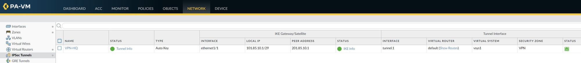
IPSec Tunnel - As you can see below, the IPSec tunnel status is turned green which means the tunnel is up and running.
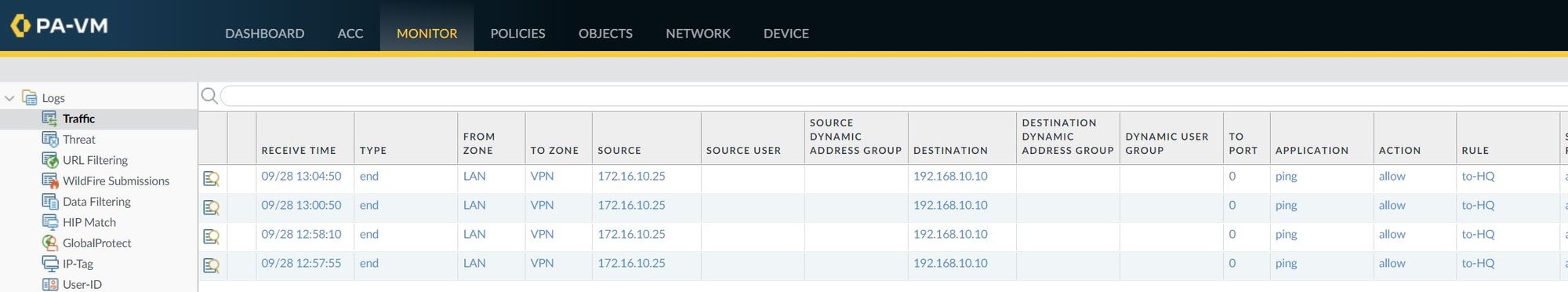
I've also attached a screenshot of the traffic logs that shows the traffic from the client to the server.
ASA
asa-lab-01# show crypto isa sa

There are no IKEv1 SAs

IKEv2 SAs:

Session-id:3, Status:UP-ACTIVE, IKE count:1, CHILD count:1

Tunnel-id Local                                               Remote                                                  Status         Role
 39578985 201.85.10.1/500                                     101.85.10.1/500                                          READY    INITIATOR
      Encr: AES-GCM, keysize: 256, Hash: N/A, DH Grp:20, Auth sign: PSK, Auth verify: PSK
      Life/Active Time: 28800/162 sec
Child sa: local selector  0.0.0.0/0 - 255.255.255.255/65535
          remote selector 0.0.0.0/0 - 255.255.255.255/65535
          ESP spi in/out: 0xe9c602ec/0xd6aeb8e6
asa-lab-01# show crypto ipsec sa peer 101.85.10.1
peer address: 101.85.10.1
Crypto map tag: __vti-crypto-map-4-0-1, seq num: 65280, local addr: 201.85.10.1
local ident (addr/mask/prot/port): (0.0.0.0/0.0.0.0/0/0)
remote ident (addr/mask/prot/port): (0.0.0.0/0.0.0.0/0/0)
current_peer: 101.85.10.1
#pkts encaps: 3, #pkts encrypt: 3, #pkts digest: 3
#pkts decaps: 3, #pkts decrypt: 3, #pkts verify: 3
#pkts compressed: 0, #pkts decompressed: 0
#pkts not compressed: 3, #pkts comp failed: 0, #pkts decomp failed: 0
#pre-frag successes: 0, #pre-frag failures: 0, #fragments created: 0
#PMTUs sent: 0, #PMTUs rcvd: 0, #decapsulated frgs needing reassembly: 0
#TFC rcvd: 0, #TFC sent: 0
#Valid ICMP Errors rcvd: 0, #Invalid ICMP Errors rcvd: 0
#send errors: 0, #recv errors: 0
local crypto endpt.: 201.85.10.1/500, remote crypto endpt.: 101.85.10.1/500
path mtu 1500, ipsec overhead 55(36), media mtu 1500
PMTU time remaining (sec): 0, DF policy: copy-df
ICMP error validation: disabled, TFC packets: disabled
current outbound spi: D6AEB8E6
current inbound spi : E9C602EC
inbound esp sas:
spi: 0xE9C602EC (3922068204)
SA State: active
transform: esp-aes-gcm-256 esp-null-hmac no compression
in use settings ={L2L, Tunnel, IKEv2, VTI, }
slot: 0, conn_id: 10403840, crypto-map: __vti-crypto-map-4-0-1
sa timing: remaining key lifetime (kB/sec): (3962879/28608)
IV size: 8 bytes
replay detection support: Y
Anti replay bitmap:
0x00000000 0x0000000F
outbound esp sas:
spi: 0xD6AEB8E6 (3601774822)
SA State: active
transform: esp-aes-gcm-256 esp-null-hmac no compression
in use settings ={L2L, Tunnel, IKEv2, VTI, }
slot: 0, conn_id: 10403840, crypto-map: __vti-crypto-map-4-0-1
sa timing: remaining key lifetime (kB/sec): (4101119/28608)
IV size: 8 bytes
replay detection support: Y
Anti replay bitmap:
0x00000000 0x00000001