

Every time I build a multicast lab, I end up using Cisco routers as the end hosts. One router acts as the multicast sender, and another acts as the receiver, even though they're not really doing any routing.
If you haven't done this before, it's quite easy to set up. On the router acting as the receiver, configure ip igmp join-group 239.1.1.1 under an interface. The router then joins the group and responds to traffic sent to it, just like a real receiver would. On the router acting as the sender, run a ping to the group address, for example ping 239.1.1.1 repeat 100, and it sends multicast packets towards the group. If everything is working, you get replies back from every router that joined the group.
This works fine, but you're essentially using a router as a host. When I share these labs, I also have to explain this setup to readers, and it can get confusing. Ideally, I want a real host that sends and receives multicast traffic, just like it would in a real network. I've tried socat and a few other tools over the years, but I never had much success with them. To be fair, they work fine, they're just a bit too complicated for my liking. When I'm learning multicast, I want to focus on multicast itself, not spend time figuring out how to get the sender and receiver working.
mcast-tools
mcast-tools is a small Python package that gives you a multicast sender and receiver you can run on any host. It comes with three main commands - mcast-send, mcast-receive and mcast-status.
mcast-sendsends a stream to a group. By default, it runs for 10 minutes at 25 packets per second.mcast-receivejoins a group and listens for the stream. By default, it does an ASM (*,G) join using IGMPv3. If you also give it a source, it does an SSM (S,G) join instead.mcast-statusshows which interfaces are joined to which groups.
You can install it with pip as always.
pip install mcast-tools
Running mcast-tools in Your Lab
If you use EVE-NG, CML or GNS3, you can install mcast-tools as a Python package on whichever host you use in your lab. However, I use Containerlab and netlab 99% of the time. Containerlab lets you build network labs using containers, and you define the whole topology in a simple YAML file. netlab sits on top of Containerlab and takes care of the configuration for you, such as IP addressing and routing protocols, so you can get a working lab up in minutes. If you're not familiar with netlab or Containerlab, I've covered them extensively here, so feel free to check them out.
I've also covered multicast in detail here. If you're new to multicast, I recommend starting there, as we won't go into the details in this post.
Building the Docker Image
When you deploy a lab with netlab, each Linux host runs as a container. I could connect to each host after the lab is up and install mcast-tools with pip, but I'd have to do this every time I start the lab, and on every host. A better option is to build a Docker image that already has mcast-tools installed, and then tell netlab to use this image for the hosts. This way, the hosts come up ready to send and receive multicast traffic.
Since mcast-tools is a Python package, I started with the python:3.13-alpine image, which is a small image that already has Python installed, and added mcast-tools on top. Here's the Dockerfile.
A Dockerfile is a simple text file that contains a set of instructions for building a Docker image. Each line is a step, such as choosing a base image, installing packages or copying files. When you build the image, Docker runs these steps in order and saves the result as a new image that you can use to start containers. If you're not familiar with Dockerfiles, just create a new directory, add a file called Dockerfile (with no extension) inside it, and paste the following content.
FROM python:3.13-alpine
RUN apk add --no-cache iproute2
RUN pip install --no-cache-dir mcast-tools==0.2.2
The first line pulls the base image. The second line installs iproute2. Alpine comes with the BusyBox version of the ip command, which doesn't support the -j (JSON output) option. mcast-tools runs ip -j to look up the IP address of an interface, so without iproute2, the lookup fails . I'll cover this issue in more detail later in the post. The last line installs mcast-tools itself. I pinned the version to 0.2.2 (which is the latest version as of writing this post) so the image always builds the same way.
Once the Dockerfile is ready, build the image with the following command. You need to run this from the directory the Dockerfile is in.
docker build -t mcast-tools:0.2.2 .
This creates a local image called mcast-tools with the tag 0.2.2, which we can then refer to in the netlab topology file.
docker images | grep mcast

mcast-tools:0.2.2                                           01e69f5b1a9d        106MB         25.5MB   U
Lab Setup
Now let's set up a lab. I'm going to use the same topology I used in my PIM Dense Mode post, which you can check out here. In the original post, I used Cisco routers as the sender and receivers. In this example, we'll replace them with Linux hosts running mcast-tools.
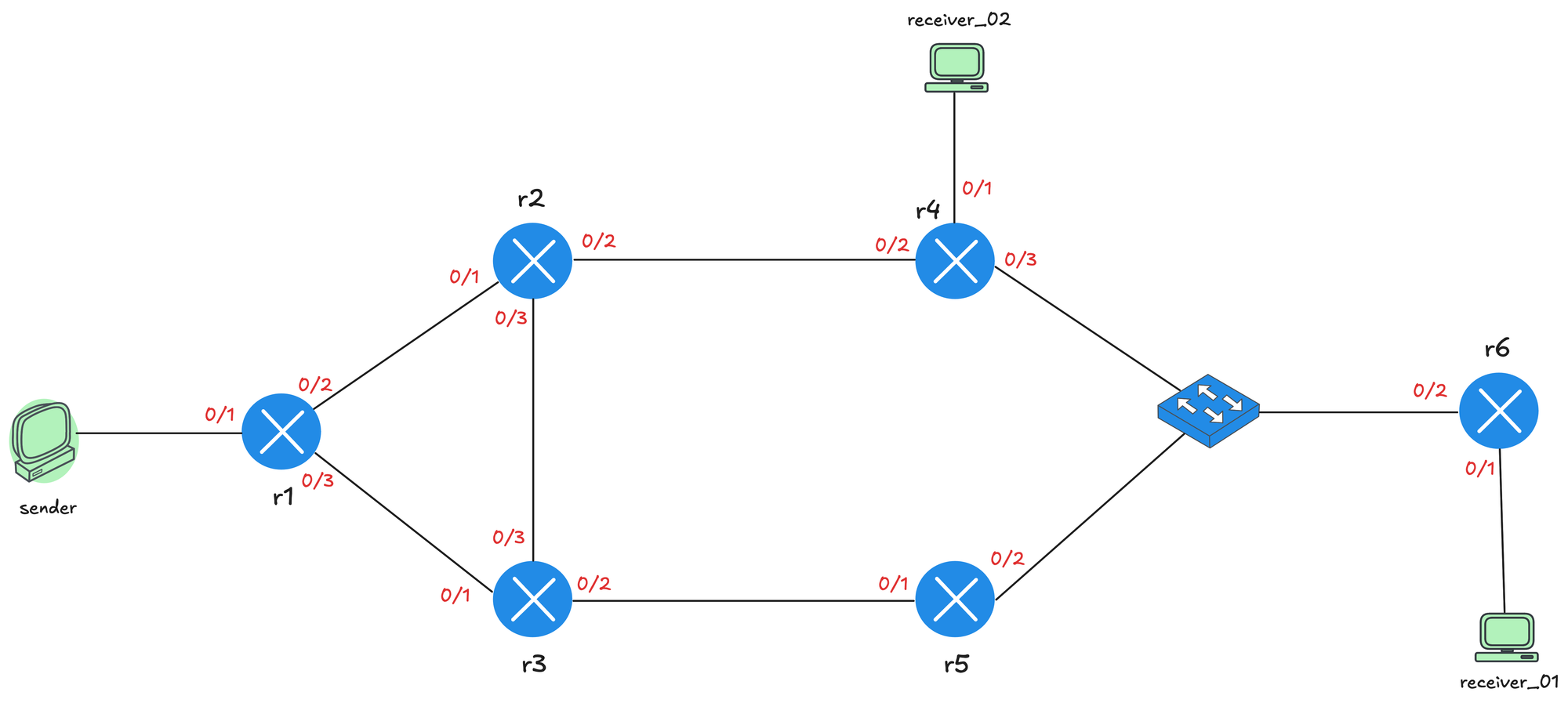
The topology has six routers. The sender connects to r1, which then connects to r2 and r3. r2 and r3 are also connected to each other. r2 connects to r4, and r3 connects to r5. r4, r5 and r6 all sit on the same segment through a switch. Finally, receiver_02 connects to r4, and receiver_01 connects to r6.
Netlab Topology File
Here's the netlab topology file I used for this lab.
plugin: [ files ]

provider: clab
defaults.device: iol
defaults.devices.iol.clab.image: containerlab:iol-17.12.01
defaults.devices.ioll2.clab.image: containerlab:iol-l2-17.12.01
defaults.devices.eos.clab.image: ceos:4.34.2

addressing:
  mgmt:
    ipv4: 192.168.202.0/24
  p2p:
    ipv4: 172.16.1.0/24
    prefix: 30

nodes:
  - name: sender
    id: 10
    device: linux
    image: mcast-tools:0.2.2
    config.inline: |
      ip route replace 10.0.0.0/8 via 10.1.0.1
  - name: r1
    module: ['ospf']
    id: 1
    config.inline: |
      no ip pim autorp
      ip multicast-routing
      !
      interface Et0/1
       ip pim dense-mode
      !
      interface Et0/2
       ip pim dense-mode
      !
      interface Et0/3
       ip pim dense-mode
  - name: r2
    module: ['ospf']
    id: 2
    config.inline: |
      no ip pim autorp
      ip multicast-routing
      !
      interface Et0/1
       ip pim dense-mode
      !
      interface Et0/2
       ip pim dense-mode
      !
      interface Et0/3
       ip pim dense-mode
      !
  - name: r3
    module: ['ospf']
    id: 3
    config.inline: |
      no ip pim autorp
      ip multicast-routing
      !
      interface Et0/1
       ip pim dense-mode
      !
      interface Et0/2
       ip pim dense-mode
      !
      interface Et0/3
       ip pim dense-mode
      !
  - name: r4
    module: ['ospf']
    id: 4
    config.inline: |
      no ip pim autorp
      ip multicast-routing
      !
      interface Et0/1
       ip pim dense-mode
      !
      interface Et0/2
       ip pim dense-mode
      !
      interface Et0/3
       ip pim dense-mode
      !
  - name: r5
    module: ['ospf']
    id: 5
    config.inline: |
      no ip pim autorp
      ip multicast-routing
      !
      interface Et0/1
       ip pim dense-mode
      !
      interface Et0/2
       ip pim dense-mode
      !
  - name: r6
    module: ['ospf']
    id: 6
    config.inline: |
      no ip pim autorp
      ip multicast-routing
      !
      interface Et0/1
       ip pim dense-mode
      !
      interface Et0/2
       ip pim dense-mode
      !
  - name: s1
    device: eos
    role: bridge
  - name: receiver_01
    id: 11
    device: linux
    image: mcast-tools:0.2.2
    config.inline: |
      ip route replace 10.0.0.0/8 via 10.1.1.1
  - name: receiver_02
    id: 12
    device: linux
    image: mcast-tools:0.2.2
    config.inline: |
      ip route replace 10.0.0.0/8 via 10.1.2.1

links:
  - prefix: 10.1.0.0/24
    sender:
      ipv4: 10.1.0.10
    r1:
      ipv4: 10.1.0.1
      ospf.passive: True
  - prefix: 10.1.1.0/24
    receiver_01:
      ipv4: 10.1.1.11
    r6:
      ipv4: 10.1.1.1
      ospf.passive: True
  - prefix: 10.1.2.0/24
    receiver_02:
      ipv4: 10.1.2.11
    r4:
      ipv4: 10.1.2.1
      ospf.passive: True
  - r1-r2
  - r1-r3
  - r2-r4
  - r3-r5
  - r2-r3
  - bridge: s1
    prefix: 172.16.2.0/24
    r4:
    r5:
    r6:
The routers are IOL nodes running OSPF, with PIM dense mode enabled on every interface. I also disabled Auto-RP with no ip pim autorp, since we don't need it for dense mode. s1 is an Arista cEOS node with the bridge role, so it acts as a simple switch connecting r4, r5 and r6.
The main focus here is the sender and the two receivers. All three are Linux nodes and they use the mcast-tools:0.2.2 image we built earlier. I also gave each host a static IP address on its link, with r1, r4 and r6 acting as their gateways. I set the router side of these links to OSPF passive, so the routers advertise the host subnets without trying to form OSPF neighbors with the hosts.
Each host also has a small inline config, which is applied by the files plugin. On the hosts, eth0 is the management interface, and the default route points out of it. This means traffic to the other lab subnets would go out the management interface instead of the lab interface (eth1). To fix this, I added a route for 10.0.0.0/8 via the connected router.
Sending Multicast Traffic
You can deploy the lab with the netlab up command. Once the lab is up, connect to the sender with netlab connect sender and run mcast-send 239.1.1.1 --interface eth1. It will start sending traffic to the group and show you a nice live output of what's happening.
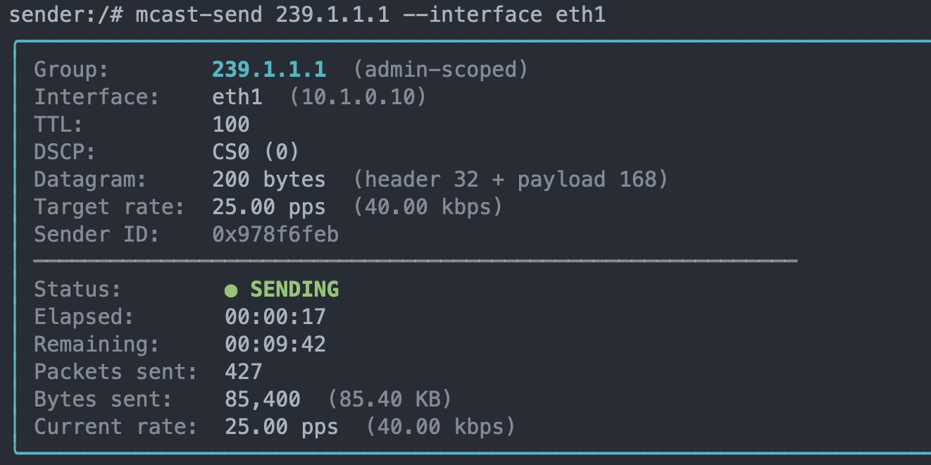
The output shows the group, the interface and source IP the traffic is going out of, the TTL, the DSCP value and the sending rate. You can also see the number of packets and bytes sent so far, and how much time is left before the stream stops.
To make sure the traffic is actually reaching the network, we can run show ip mroute on r1.
r1#show ip mroute
IP Multicast Routing Table

 Timers: Uptime/Expires
 Interface state: Interface, Next-Hop or VCD, State/Mode

(*, 239.1.1.1), 00:00:39/stopped, RP 0.0.0.0, flags: D
  Incoming interface: Null, RPF nbr 0.0.0.0
  Outgoing interface list:
    Ethernet0/3, Forward/Dense, 00:00:39/stopped, flags:
    Ethernet0/2, Forward/Dense, 00:00:39/stopped, flags:

(10.1.0.10, 239.1.1.1), 00:00:39/00:02:20, flags: T
  Incoming interface: Ethernet0/1, RPF nbr 0.0.0.0
  Outgoing interface list:
    Ethernet0/2, Forward/Dense, 00:00:39/stopped, flags:
    Ethernet0/3, Forward/Dense, 00:00:39/stopped, flags:
r1 has created an (S,G) entry for (10.1.0.10, 239.1.1.1), which means it's receiving the stream from the sender. The incoming interface is Ethernet0/1, which is the link to the sender. Since we're running dense mode, r1 floods the traffic out of both Ethernet0/2 and Ethernet0/3 towards r2 and r3.
Receiving Multicast Traffic
Now, I can go to receiver_01, for example, and run mcast-receive 239.1.1.1 --interface eth1. The host sends an IGMP join for the group, and as soon as the traffic arrives, you can see the stream details in the output.
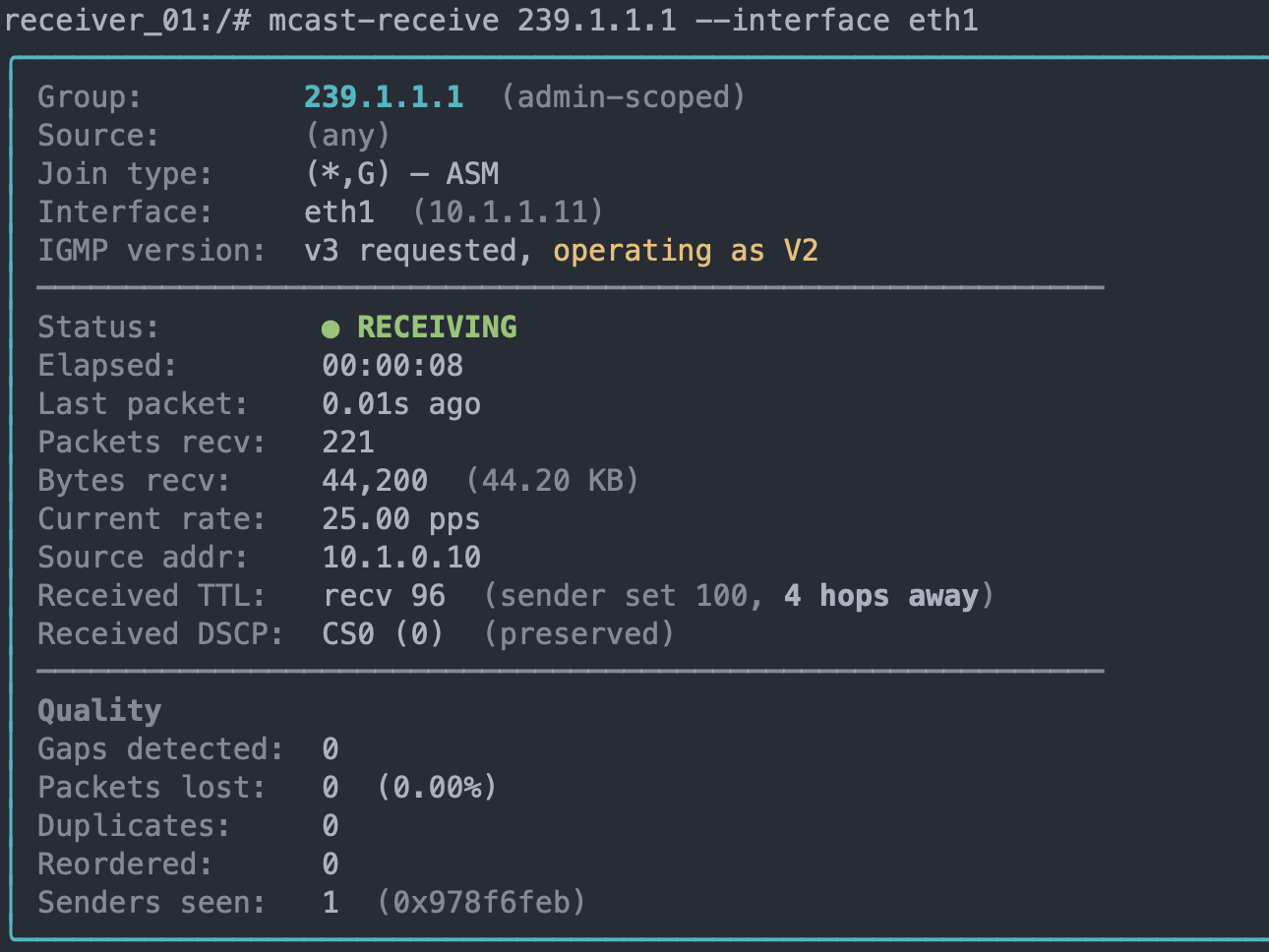
Since I didn't specify a source, the receiver does an ASM (*,G) join. You may notice the IGMP version says "v3 requested, operating as V2". mcast-receive uses IGMPv3 by default, but r6 is sending IGMPv2 queries (the default on Cisco IOS), so the host falls back to v2. If you want to use IGMPv3, for example to test SSM, you need to configure ip igmp version 3 on r6's interface facing the receiver.
The receiver is getting the stream at 25 pps from the source 10.1.0.10, which matches what we set on the sender. The received TTL is 96, and since the sender set it to 100, we know the packets went through 4 routers to get here (r1 > r3 > r5 > r6). The DSCP value was also preserved along the way.
You can also open another terminal, connect to the same receiver with netlab connect receiver_01, and run mcast-status while mcast-receive is still running.

Here, we can see that eth1 has joined 239.1.1.1. The IGMP column shows the version the host is actually using, which is V2, and the Forced column shows v3, which is the version mcast-receive asked for. This matches what we saw earlier, where the host fell back to v2 because of r6's queries.
There are no IPv6 groups listed because, by default, mcast-status hides the all-nodes and solicited-node groups that every IPv6 host joins. If you want to see those as well, you can add the --all flag.
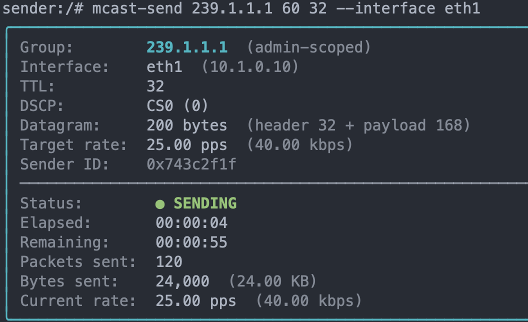
By default, mcast-send runs for 10 minutes. If you want to change this, you can pass the duration in seconds right after the group. For example, mcast-send 239.1.1.1 60 --interface eth1 sends the stream for 60 seconds. You can also change the TTL by adding it after the duration, so mcast-send 239.1.1.1 60 32 --interface eth1 sends the stream for 60 seconds with a TTL of 32.
If you want to test SSM, you can pass the source address to mcast-receive For example, mcast-receive 232.1.1.1 --source 10.1.0.10 --interface eth1 does an (S,G) join for the group, and the host only accepts traffic from 10.1.0.10. Keep in mind that SSM needs IGMPv3, so the last-hop router's interface facing the receiver must be set to ip igmp version 3, and the routers need to be configured for SSM as well.
Why We Added iproute2
Earlier, I mentioned that I added iproute2 to the Docker image. When I first built the image without it, I passed --interface eth1 to mcast-send, but I got the warning could not resolve IPv4 address for eth1, and it didn't work.
The reason is that mcast-tools looks up the IP address of the interface by running ip -j, which returns the output in JSON format. The Alpine image comes with the BusyBox version of the ip command, which is a cut-down version and doesn't support the -j option. So the lookup failed, mcast-tools couldn't bind to eth1
Installing iproute2 replaces the BusyBox ip command with the full version, which supports JSON output. Once I rebuilt the image with it, mcast-tools picked up the correct interface and the traffic went out of eth1 as expected. You can quickly check this in your own image by running ip -j -4 addr show dev lo. If it prints JSON, you're good to go.