
In this post, we will look at Source Specific Multicast, or SSM. This is a different approach to multicast that simplifies the overall architecture by removing the need for an RP entirely.
In the previous posts, we covered PIM Sparse Mode, where receivers join a shared tree rooted at the RP and then optionally switch to the shortest path tree toward the source. We also looked at Auto-RP and BSR, which solve the problem of dynamically distributing RP information to all routers. SSM takes a different approach by eliminating the shared tree concept altogether.

Any Source Multicast (ASM)
Before we look at SSM, let's briefly talk about Any Source Multicast, or ASM. This is the traditional multicast model we have been using throughout this series.
With ASM, receivers join a multicast group without specifying a source. They simply say 'I want traffic for group 239.1.1.1' and the network figures out how to deliver traffic from any source sending to that group. This is why it is called Any Source Multicast.
ASM relies on an RP to connect sources and receivers. Receivers join the shared tree rooted at the RP, and sources register with the RP so their traffic can reach the shared tree. Once traffic is flowing, routers can optionally switch to the shortest path tree for efficiency.
The downside of ASM is the complexity of managing the RP. You need to either configure the RP statically on every router or use a dynamic mechanism like Auto-RP or BSR. SSM removes this complexity entirely by eliminating the RP from the picture.
SSM Overview
Source-specific multicast uses a subset of PIM sparse mode and IGMPv3 to allow a client to receive multicast traffic directly from the source. SSM uses the PIM sparse-mode functionality to create the shortest path tree (SPT) between the receiver and the source without the help of an RP.
With SSM, receivers specify both the multicast group and the source address they want to receive traffic from. Instead of joining (*, G) and relying on the RP to connect them to sources, receivers join (S, G) directly. The last hop router builds the shortest path tree toward the source immediately, without involving an RP at any point.
This makes SSM simpler to deploy and more secure. There is no RP to configure or protect, no shared tree to build, and receivers only get traffic from sources they explicitly request. The trade-off is that receivers must know the source address in advance. The default SSM range is 232.0.0.0/8. You can also configure additional addresses using the ip pim ssm acl command with an ACL to define custom groups.
IGMPv3
For SSM to work, receivers must be able to tell the last hop router (LHR) which source they want to receive traffic from. IGMPv1 and IGMPv2 do not support this. When a host sends an IGMPv2 membership report, it only contains the group address. The router learns that someone on the segment wants traffic for that group, but it has no idea which source the receiver is interested in.
IGMPv3 adds source filtering to solve this problem. When a host sends an IGMPv3 membership report, it can include a list of sources it wants to receive from. This is called an include mode report, where the host says, 'I want traffic for this group, but only from these specific sources.' The host can also use exclude mode to say, 'I want traffic for this group from any source except these.'
For SSM, receivers use the include mode with a single source address. The last hop router receives this report and knows exactly which (S, G) tree to join. It sends a PIM join directly toward the source without ever contacting an RP.
Source-Specific Multicast Quick Reference
- SSM uses PIM sparse mode mechanics but without an RP
- Receivers must specify both the group and the source address
- IGMPv3 is required on the LHR
- Default SSM range is 232.0.0.0/8
- Enable SSM on the LHR with
ip pim ssm default - Enable IGMPv3 on receiver-facing interfaces with
ip igmp version 3 - Only (S, G) state is created, no (*, G) shared tree
- PIM joins go directly toward the source, not the RP
- Receivers join with
ip igmp join-group <group> source <source>
Source Specific Multicast Lab
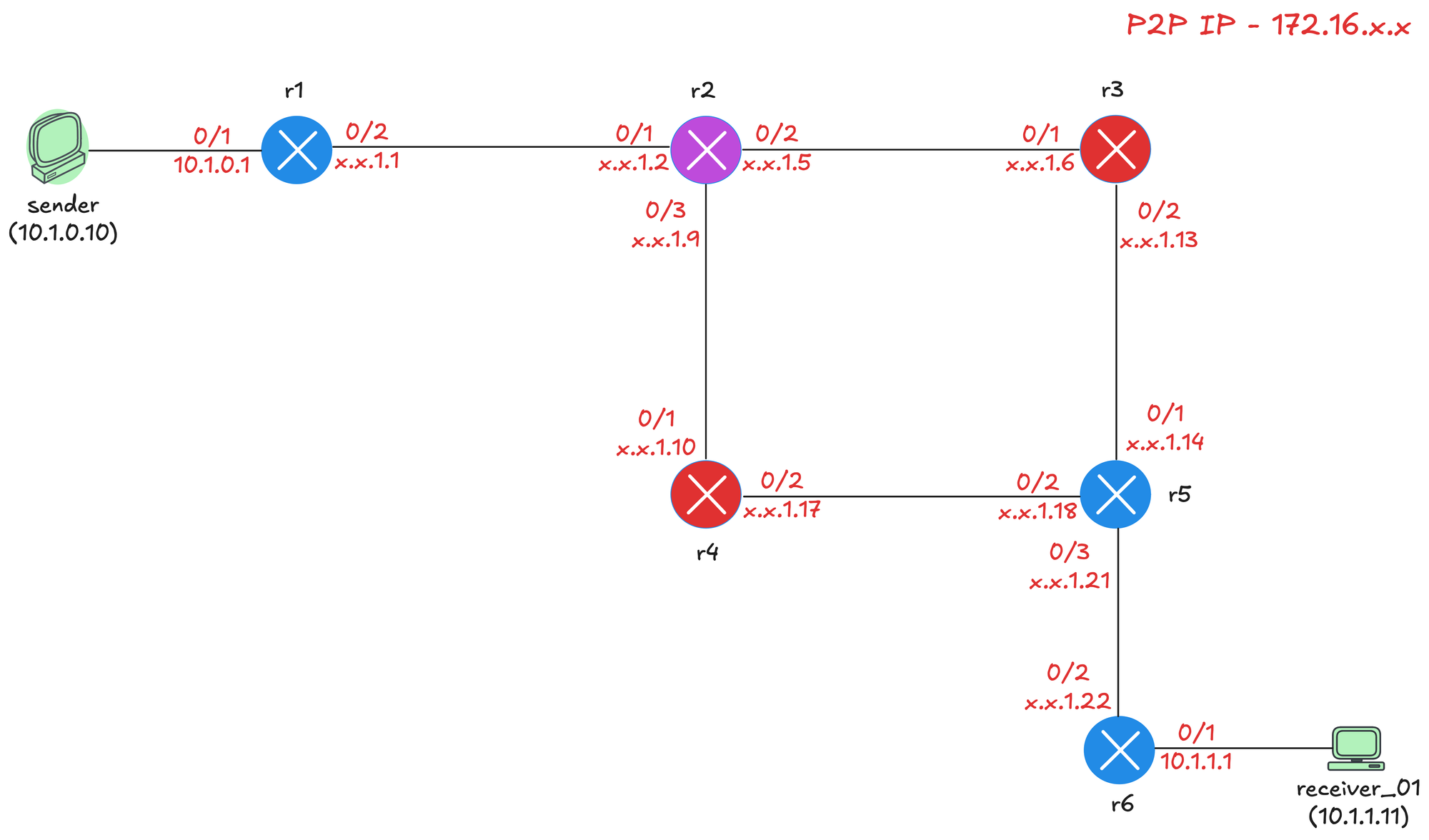
We will use the following topology for this lab. We have six routers with the sender connected to r1 and the receiver connected to r6. The sender has the IP address 10.1.0.10 and the receiver has 10.1.1.11. All point-to-point links use the 172.16.x.x range for IP addressing. Each router has a loopback interface with the address 10.0.0.x, where x is the router number. For example, r3 has 10.0.0.3, r4 has 10.0.0.4, and so on.

Initial Configs
In this topology, r1 is the First Hop Router (FHR) since it is directly connected to the sender. r6 is the Last Hop Router (LHR) since it is directly connected to the receiver. OSPF is enabled on all interfaces, so we have full unicast reachability across the network. PIM sparse mode is also enabled on all interfaces, including the loopbacks.
On top of that, multicast routing is enabled globally on every router, and Auto-RP is disabled. Here is the sample config from r2 as a reference.
! r2
ip multicast-routing
no ip pim autorp
!
router ospf 1
router-id 10.0.0.2
!
interface Loopback0
ip address 10.0.0.2 255.255.255.255
ip pim sparse-mode
ip ospf 1 area 0.0.0.0
!
interface Ethernet0/1
description r2 -> r1
ip address 172.16.1.2 255.255.255.252
ip pim sparse-mode
ip ospf network point-to-point
ip ospf 1 area 0.0.0.0
!
interface Ethernet0/2
description r2 -> r3
ip address 172.16.1.5 255.255.255.252
ip pim sparse-mode
ip ospf network point-to-point
ip ospf 1 area 0.0.0.0
!
interface Ethernet0/3
description r2 -> r4
ip address 172.16.1.9 255.255.255.252
ip pim sparse-mode
ip ospf network point-to-point
ip ospf 1 area 0.0.0.0SSM Configuration
For SSM to work, we need to enable IGMPv3 on the LHR interface facing the receiver. By default, Cisco IOS uses IGMPv2, so we need to change this with the ip igmp version 3 command on r6's Ethernet0/1 interface. We also need to enable SSM on the LHR by running ip pim ssm default in global configuration. This tells the router to use SSM for the default 232.0.0.0/8 range.
! r6
interface Ethernet0/1
description r6 -> receiver_01
ip address 10.1.1.1 255.255.255.0
ip pim sparse-mode
ip igmp version 3
ip ospf network point-to-point
ip ospf 1 area 0.0.0.0
!
ip pim ssm defaultIn this lab, we are using Cisco IOS routers as both the sender and receiver, but IP routing is disabled on them, so they function as end devices. From the sender, you can simply ping a multicast address like 232.1.1.1 to simulate multicast traffic.
! sender
ping 232.1.1.1 repeat 5On the receiver side, we also enable IGMPv3 on the interface that connects to the LHR. To join a multicast group, you run the ip igmp join-group 232.1.1.1 source 10.1.0.10 command. The important difference here is that we are specifying the source address. In the previous posts, we never specified a source when joining a group. With SSM, the receiver must tell the LHR exactly which source it wants to receive traffic from.
receiver_01(config)#interface Et0/1
receiver_01(config)#ip igmp version 3
receiver_01(config-if)#ip igmp join-group 232.1.1.1 source 10.1.0.10PIM Join
When the receiver joins the group with the source specified, r6 sends a PIM Join (S,G) directly toward the source. This is different from PIM sparse mode where the LHR first sends a (*, G) join toward the RP. With SSM, there is no RP involved, so the join goes straight toward the source.
The packet capture shows r6 sending a PIM Join/Prune message to 224.0.0.13. The message contains the group address 232.1.1.1/32 and the source address 10.1.0.10. The upstream neighbor is 172.16.1.21, which is r5.

Each router along the path performs an RPF check to determine where to send the join. The RPF lookup on r5 shows that the path to reach 10.1.0.10 is via Ethernet0/2 toward r4.
r5#show ip rpf 10.1.0.10
RPF information for sender (10.1.0.10)
RPF interface: Ethernet0/2
RPF neighbor: r4 (172.16.1.17)
RPF route/mask: 10.1.0.0/24
RPF type: unicast (ospf 1)
Doing distance-preferred lookups across tables
RPF topology: ipv4 multicast base, originated from ipv4 unicast base
Based on RPF, the join travels the path r6 > r5 > r4 > r2 > r1, building the shortest path tree from the receiver all the way to the FHR. Once the join reaches r1, the tree is complete. Multicast traffic from the sender flows down the tree directly to the receiver without ever touching an RP.
The multicast routing table on r6 confirms SSM is working. Notice there is only an (S, G) entry for (10.1.0.10, 232.1.1.1) and no (*, G) entry. This is the key difference with SSM. There is no shared tree, so no (*, G) state is created.
r6#show ip mroute
IP Multicast Routing Table
Flags: D - Dense, S - Sparse, B - Bidir Group, s - SSM Group, C - Connected,
L - Local, P - Pruned, R - RP-bit set, F - Register flag,
T - SPT-bit set, J - Join SPT, M - MSDP created entry, E - Extranet,
X - Proxy Join Timer Running, A - Candidate for MSDP Advertisement,
U - URD, I - Received Source Specific Host Report,
Z - Multicast Tunnel, z - MDT-data group sender,
Y - Joined MDT-data group, y - Sending to MDT-data group,
G - Received BGP C-Mroute, g - Sent BGP C-Mroute,
N - Received BGP Shared-Tree Prune, n - BGP C-Mroute suppressed,
Q - Received BGP S-A Route, q - Sent BGP S-A Route,
V - RD & Vector, v - Vector, p - PIM Joins on route,
x - VxLAN group, c - PFP-SA cache created entry,
* - determined by Assert, # - iif-starg configured on rpf intf,
e - encap-helper tunnel flag, l - LISP decap ref count contributor
Outgoing interface flags: H - Hardware switched, A - Assert winner, p - PIM Join
t - LISP transit group
Timers: Uptime/Expires
Interface state: Interface, Next-Hop or VCD, State/Mode
(10.1.0.10, 232.1.1.1), 00:03:45/00:02:46, flags: sTI
Incoming interface: Ethernet0/2, RPF nbr 172.16.1.21
Outgoing interface list:
Ethernet0/1, Forward/Sparse, 00:03:45/00:02:46, flags: The flags show s which indicates this is an SSM group, T which means the SPT bit is set, and I which means the router received a source-specific host report via IGMPv3. The incoming interface is Ethernet0/2 toward r5, and the outgoing interface is Ethernet0/1 toward the receiver.
The IGMP groups output on r6 shows the receiver has joined group 232.1.1.1 with the SSM flag set. The group mode is INCLUDE, which means the receiver is specifying exactly which sources it wants to receive from. The source list shows 10.1.0.10, which is our sender. The R flag indicates this is a remote report received from the receiver at 10.1.1.11.
r6#show ip igmp groups detail
Flags: L - Local, U - User, SG - Static Group, VG - Virtual Group,
SS - Static Source, VS - Virtual Source,
Ac - Group accounted towards access control limit
Interface: Ethernet0/1
Group: 232.1.1.1
Flags: SSM
Uptime: 08:58:26
Group mode: INCLUDE
Last reporter: 10.1.1.11
Group source list: (C - Cisco Src Report, U - URD, R - Remote, S - Static,
V - Virtual, M - SSM Mapping, L - Local,
Ac - Channel accounted towards access control limit)
Source Address Uptime v3 Exp CSR Exp Fwd Flags
10.1.0.10 08:58:26 00:02:08 stopped Yes RIf we check the multicast routing table on r3, there is no entry. This is because r3 is not in the path between the source and the receiver. The SPT follows the shortest path based on RPF, which is r6 > r5 > r4 > r2 > r1. Since r3 is not part of this path, it never receives a PIM join and has no multicast state for this group.
r3#show ip mr
IP Multicast Routing Table
Flags: D - Dense, S - Sparse, B - Bidir Group, s - SSM Group, C - Connected,
L - Local, P - Pruned, R - RP-bit set, F - Register flag,
T - SPT-bit set, J - Join SPT, M - MSDP created entry, E - Extranet,
X - Proxy Join Timer Running, A - Candidate for MSDP Advertisement,
U - URD, I - Received Source Specific Host Report,
Z - Multicast Tunnel, z - MDT-data group sender,
Y - Joined MDT-data group, y - Sending to MDT-data group,
G - Received BGP C-Mroute, g - Sent BGP C-Mroute,
N - Received BGP Shared-Tree Prune, n - BGP C-Mroute suppressed,
Q - Received BGP S-A Route, q - Sent BGP S-A Route,
V - RD & Vector, v - Vector, p - PIM Joins on route,
x - VxLAN group, c - PFP-SA cache created entry,
* - determined by Assert, # - iif-starg configured on rpf intf,
e - encap-helper tunnel flag, l - LISP decap ref count contributor
Outgoing interface flags: H - Hardware switched, A - Assert winner, p - PIM Join
t - LISP transit group
Timers: Uptime/Expires
Interface state: Interface, Next-Hop or VCD, State/ModeClosing Up
In this post, we covered Source Specific Multicast, which simplifies multicast by removing the need for an RP. Receivers specify both the group and the source they want, and the network builds the shortest path tree directly toward the source.
This brings us to the very tail end of the multicast series. We started with the basics of multicast, moved through IGMP, PIM Dense Mode, PIM Sparse Mode, Auto-RP, BSR, and finally SSM. Each topic built on the previous one.