Recently, I was doing some reading on MPLS and wanted to build a lab for it. For my use case, I needed five routers connected and running OSPF between them before I could even start configuring MPLS. So before doing any MPLS work, I have to spend a lot of time setting up the lab and prerequisites like configuring IP addresses on interfaces and setting up OSPF. This is tedious, and this is exactly where Netlab can help you get up to speed.
Netlab is an open source tool that makes it easy to build and share network labs. Instead of manually dragging devices in a GUI or typing the same base configs over and over, you describe your lab in a simple YAML file. Netlab then takes care of creating the topology, assigning IP addresses, configuring routing protocols, and even pushing custom configs. Netlab works with containerlab (or vagrant) so you can spin up realistic network topologies in minutes and reproduce them anywhere automagically.

Creating Network Labs the Usual Way
As Network Engineers, we often set up labs to help us learn and practice. Most of us use tools like EVE-NG, GNS3, or Cisco CML, where you go into a web GUI, create a lab, start adding nodes, connect links, boot them up, and then begin configuring. This typically involves adding hostnames, configuring management IP addresses, and completing other initial setup tasks.
There are some challenges with this approach. Depending on how you like to build labs, it may not be a problem for you. But for people like me, I don’t enjoy this process. I create a lot of labs, especially when I write blogs, and I want them to be easy to share and reproduce. If I build a lab in EVE-NG, for example, I need to find a way to recreate it, and that’s not always straightforward. Again, this might not be a concern for your use case, but it is for mine.
Containerlab (My Favourite)
Containerlab, which is another tool for building labs and is also my favourite, tries to solve this problem by taking a different approach. With containerlab, you define the lab in a YAML file. Yes, you define it as plain text, including device names and links. Anyone can reproduce the lab just by using this one YAML file. When you deploy a lab with containerlab, it already comes preconfigured with hostnames, management IP addresses, and other useful settings. I’ve already covered containerlab in detail in my previous blog posts, so feel free to check those out below.
Even with containerlab, I still have to configure the rest of the lab manually. For example, if I want to test OSPF, I usually spin up a containerlab topology and once the devices are running, I log in to each one to configure point-to-point link IPs, loopback IPs, and so on. This can get tedious. Of course, if you’re a beginner, you should go through the process and learn how to configure everything by hand. But I’ve done it hundreds of times, and I really don’t want to keep repeating the same setup over and over again.
How Netlab Solves These Issues?
Netlab tries to address these issues by letting you define your topology at a very high level, and then it automatically generates not only the containerlab topology but also the actual device configurations. If you prefer, you can also use Vagrant instead of containerlab.
To kick things off, let’s say I want four Arista routers already preconfigured with interface IPs, loopbacks, and OSPF. When I spin up the lab and log in, I want OSPF to already be running between them. All I need is the topology file shown below, and Netlab takes care of the rest. It still uses containerlab under the hood to deploy the lab, but then it uses Ansible to push the actual device configuration. All of this is hidden from us and abstracted away.
provider: clab
defaults.device: eos
defaults.devices.eos.clab.image: ceos:4.34.2

module: [ ospf ]

nodes: [r1, r2, r3, r4]

links:
  - r1-r2
  - r2-r3
  - r3-r4
Here we are saying - use OSPF, create four nodes, define the links as shown, and use Arista as the platform. I can share this file with someone else, and all they need to do is run a single command. The lab will be up and running in just a few minutes.
Netlab Installation and Initial Setup
Throughout this post, I will be using an Ubuntu 22.04 server freshly installed with 16 GB of RAM and 4 CPUs. I also assigned 64 GB of disk. At a high level,
- You need to install Netlab, which is just a Python package.
- If you plan to use containerlab, Netlab can install it for you, or you can install it separately, but we’ll go with the first option.
- You also need Ansible, and again, Netlab can install that for you as well.
- If you are going to use Arista, you will need to download the image from the Arista website and import it as a Docker image.
- You can also download and use other images as you wish (Cisco or Juniper, for example)
Install Netlab
As mentioned earlier, Netlab is just a Python package, so you can install it with pip. Make sure you have Python 3 and pip installed. Ubuntu 22.04 already comes with Python 3.10, but you still need to install pip.
sudo apt update
sudo apt install python3-pip -y
pip install networklab
Now, if you run netlab version, you should see the version, which confirms that the installation was successful. If you get any errors, try logging out and back in. Make sure you can see the Netlab version before proceeding.
suresh@netlab:~$ netlab version
netlab version 25.07
Install Containerlab and Ansible
If you run netlab install, you’ll see a few options to install the required tools like containerlab and Ansible. You can install them separately, but Netlab makes it easier to do it directly through the netlab command.
suresh@netlab:~$ netlab install
┏━━━━━━━━━━━━━━┳━━━━━━━━━━━━━━━━━━━━━━━━━━━━━━━━━━━━━━━━━━━━━━━━━━━┓
┃ Script       ┃ Installs                                          ┃
┡━━━━━━━━━━━━━━╇━━━━━━━━━━━━━━━━━━━━━━━━━━━━━━━━━━━━━━━━━━━━━━━━━━━┩
│ ubuntu       │ Mandatory and nice-to have Debian/Ubuntu packages │
│ libvirt      │ QEMU, KVM, libvirt, and Vagrant                   │
│ containerlab │ Docker and containerlab                           │
│ ansible      │ Ansible and prerequisite Python libraries         │
│ grpc         │ GRPC libraries and Nokia GRPC Ansible collection  │
└──────────────┴───────────────────────────────────────────────────┘
netlab install ubuntu
netlab install ansible
netlab install containerlabAt this point, you should also check the Ansible and containerlab versions to make sure they are installed correctly before proceeding.
suresh@netlab:~$ ansible --version
ansible [core 2.17.13]
  config file = None
  configured module search path = ['/home/suresh/.ansible/plugins/modules']
  ansible python module location = /usr/local/lib/python3.10/ansible
  ansible collection location = /usr/share/ansible/collections
  executable location = /usr/local/bin/ansible
  python version = 3.10.12
  jinja version = 3.1.6
  libyaml = True
suresh@netlab:~$ containerlab version
____ ___ _ _ _____ _ ___ _ _ _____ ____ _ _
/ ___/ _ \| \ | |_ _|/ \ |_ _| \ | | ____| _ \| | __ _| |__
| | | | | | \| | | | / _ \ | || \| | _| | |_) | |/ _` | '_ \
| |__| |_| | |\ | | |/ ___ \ | || |\ | |___| _ <| | (_| | |_) |
\____\___/|_| \_| |_/_/ \_\___|_| \_|_____|_| \_\_|\__,_|_.__/
version: 0.68.0
commit: a90b6684
date: 2025-05-05T15:36:49Z
source: https://github.com/srl-labs/containerlab
rel. notes: https://containerlab.dev/rn/0.68/Download and Import Arista Image
Next, we need to download the Arista image and import it as a Docker image. I’m going to use cEOS Lab 4.34.2F, but if you have a different version, that works fine as well.
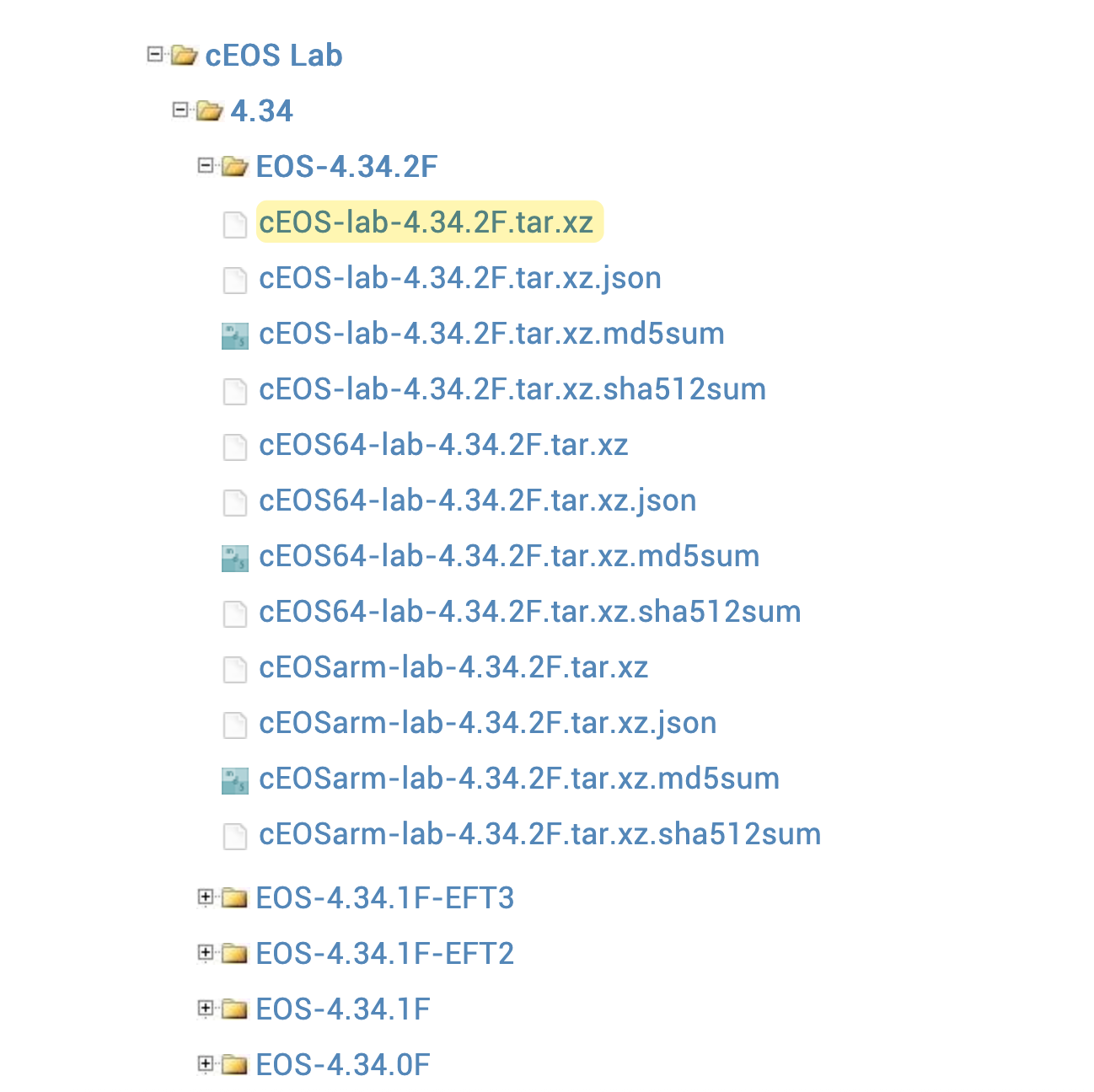
Head over to the Arista download page, log in with your account (or create a new one), and download the image. Once downloaded, copy the image to your Ubuntu VM (for example, using SCP) and import it by running the docker import command.
docker import cEOS-lab-4.34.2F.tar.xz ceos:4.34.2Wait a few minutes, and then run docker images and you should now see the Arista image. With all of this in place, we are good to go.
suresh@netlab:~$ docker images
REPOSITORY              TAG            IMAGE ID       CREATED        SIZE
ceos                    4.34.2         5e8f3776cf94   13 hours ago   2.18GB
Please check out my other blog post on how to import Cisco IOL images into Containerlab and use them with Netlab.

Setting up the First Lab
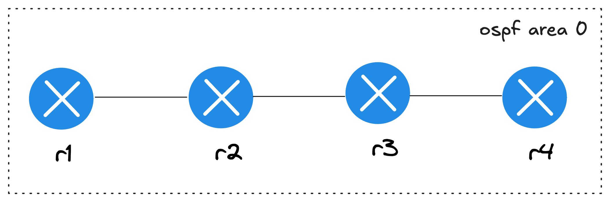
Now that we have all the prerequisites in place, let’s go ahead and deploy our first lab with four routers, all in OSPF area 0.
provider: clab
defaults.device: eos
defaults.devices.eos.clab.image: ceos:4.34.2

module: [ ospf ]
nodes: [r1, r2, r3, r4]
links:
  - r1-r2
  - r2-r3
  - r3-r4
In this topology.yml file, we are using containerlab (clab) as the provider to manage the lab under the hood. You could also use Vagrant if you prefer. We then set the default device type to eos and point it to the Docker image we want to use.
Next, we include one of the available configuration modules, ospf, which tells Netlab to configure OSPF for us. You have the flexibility to tweak OSPF parameters like process ID, area, passive interfaces, or router IDs, but for now, we’ll stick with the defaults. Finally, we define the nodes, in this case four devices, and the links between them. For example, r1 connects to r2, r2 connects to r3, and r3 connects to r4.
Now you just run one command netlab up and that’s it. It takes a few minutes for the lab to come online. First, it deploys the lab with containerlab, and then it runs a series of Ansible tasks to configure the devices as defined in the topology file.
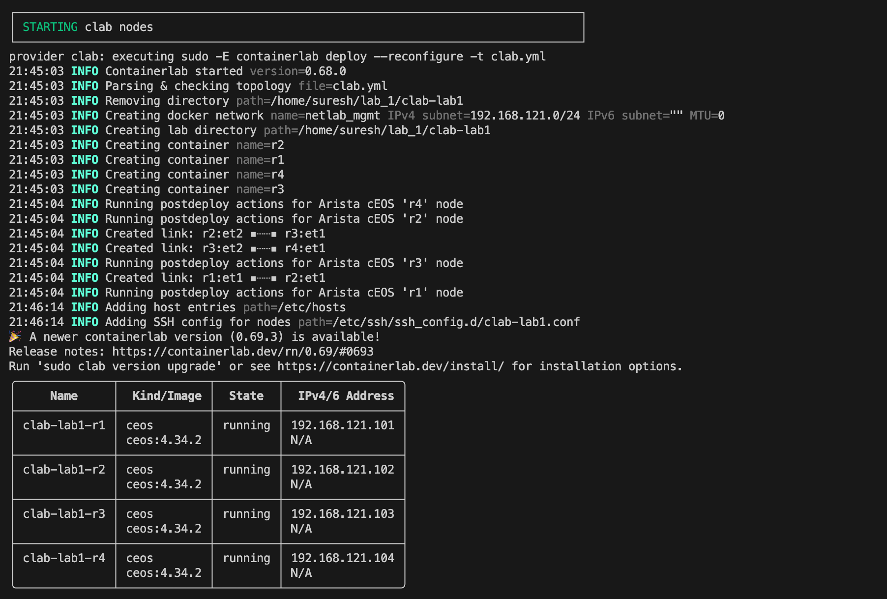
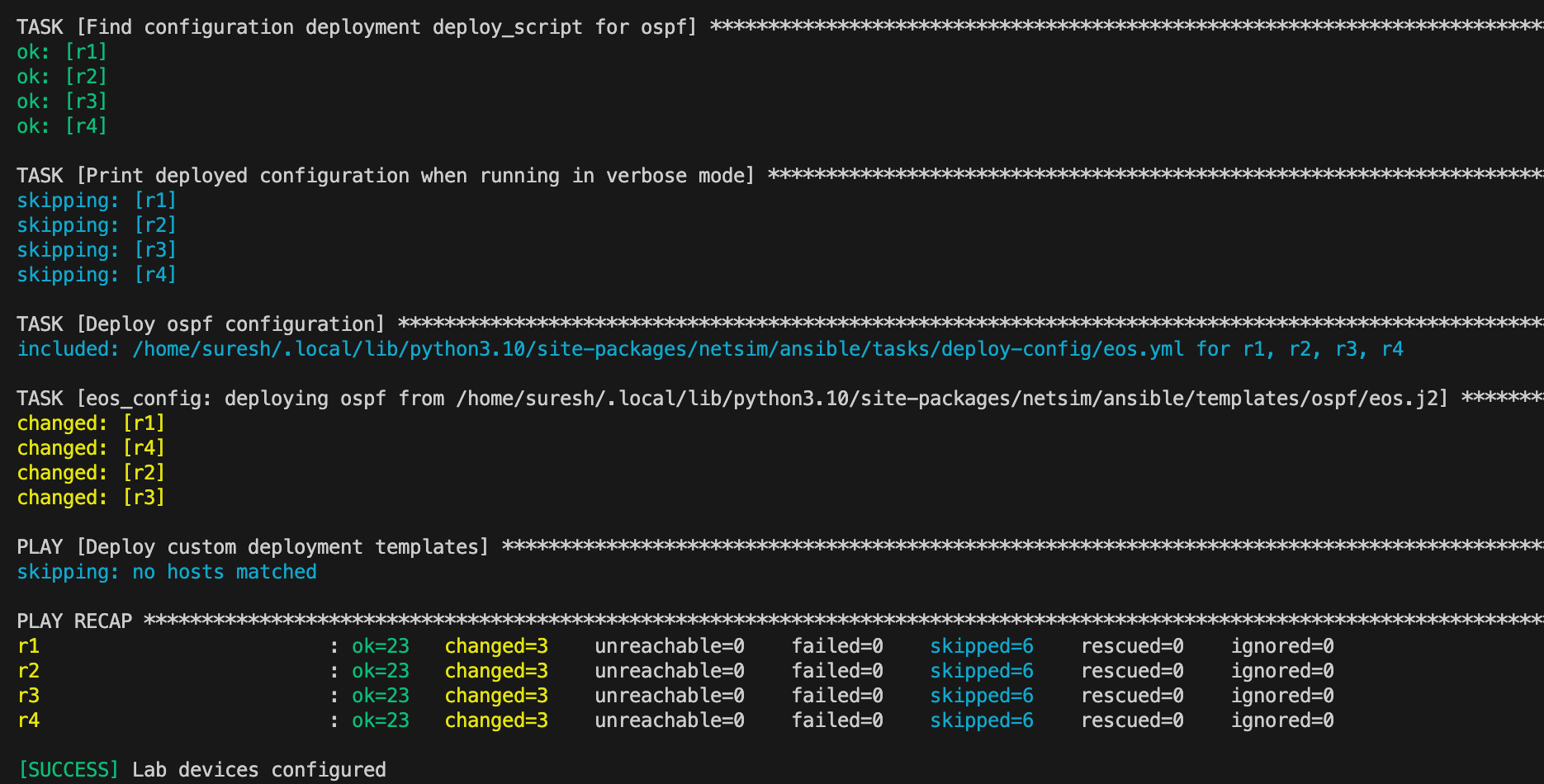
You’ll also see a summary of the management IP addresses that were assigned. By default, Netlab uses 192.168.121.0/24 for management.
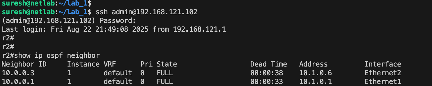
If you SSH into the devices, you’ll see that the IP addresses are already configured, OSPF neighbour relationships are established, and everything is set up exactly as we wanted.
You will also notice that in the current directory, Netlab creates a bunch of files such as the containerlab topology file, the Ansible inventory file, and the group_vars and host_vars directories. Once you are done with the lab, you can run netlab down to bring down the lab, but the files it created will stay, so you can redeploy the lab later. If you want to completely remove everything, you can use the --cleanup flag to destroy all the files as well.
netlab down --cleanupnetlab down, with or without the --cleanup option, your lab is gone along with its configuration. So, please keep this in mind.Netlab IP Addressing
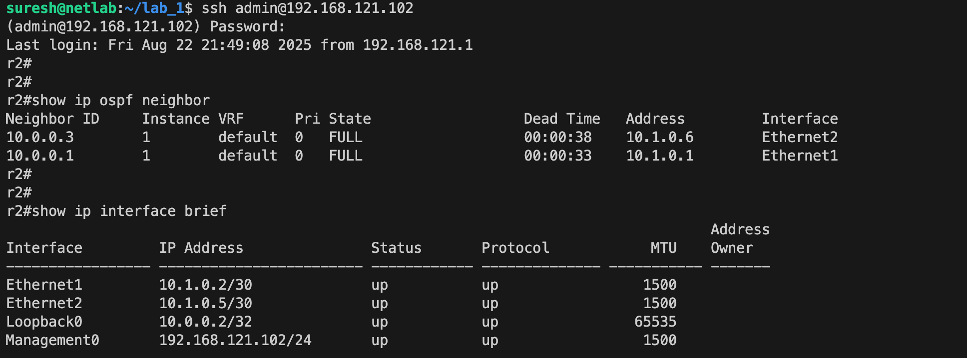
From the previous example, you might have noticed that Netlab uses 192.168.121.0/24 for management, 10.0.0.0/24 for loopbacks (as seen in the OSPF output), and 10.1.0.0/16 for point-to-point IP addresses. If this doesn’t align with your setup, you can change it.
You can customize the addressing by using the addressing section. In this example, I’m changing the management network to 192.168.200.0/24 and point-to-point to 172.16.1.0/24, with /30 subnets assigned to each link.
provider: clab
defaults.device: eos
defaults.devices.eos.clab.image: ceos:4.34.2

addressing:
  mgmt:
    ipv4: 192.168.200.0/24
  p2p:
    ipv4: 172.16.1.0/24
    prefix: 30

module: [ ospf ]
nodes: [r1, r2, r3, r4]
links:
  - r1-r2
  - r2-r3
  - r3-r4
When we redeploy the lab and check the addressing, the changes are reflected as expected. You can use netlab status command to display the state of lab instances running on the current server
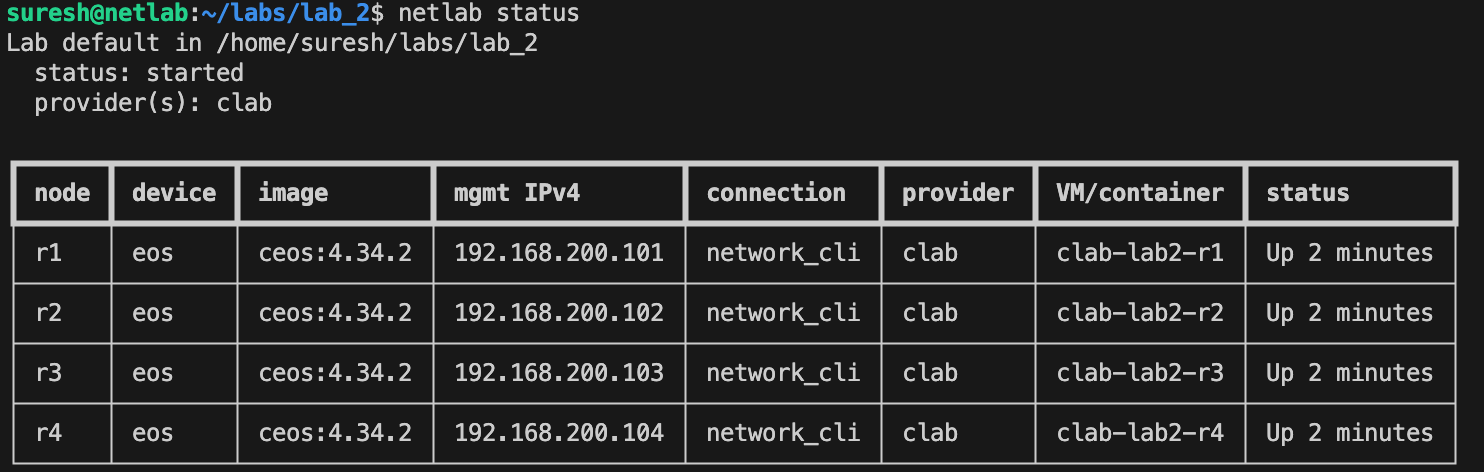
Here is the output from r2 for example. You can either SSH to a device directly using its management IP, for example ssh admin@192.168.200.102, or you can use the Netlab helper command by specifying the node name, such as netlab connect r2.
r2#show ip interface brief

Interface         IP Address               Status       Protocol      MTU
----------------- ------------------------ ------------ ---------- -------
Ethernet1         172.16.1.2/30            up           up            1500
Ethernet2         172.16.1.5/30            up           up            1500
Loopback0         10.0.0.2/32              up           up           65535
Management0       192.168.200.102/24       up           up            1500
Custom Device Configurations
Now, let’s say we have a lab up and running, but want to push extra configuration to all devices, such as NTP, DNS, AAA, or anything similar. Of course, we could log in to each device and run the commands manually, but that takes away the whole point of automation. Netlab provides an easier way to do this using the netlab config command on an already running lab.
For example, if I want to add ntp server 1.1.1.1 to all four routers, I can create a Jinja2 file called ntp.j2 in the same directory as the topology file, with the desired configuration inside. Then I simply run netlab config ntp and Netlab applies the configuration from the Jinja2 file to all devices using Ansible.
First, create the ntp.j2 file with the appropriate config.
ntp server 1.1.1.1Then, run the following command.
netlab config ntp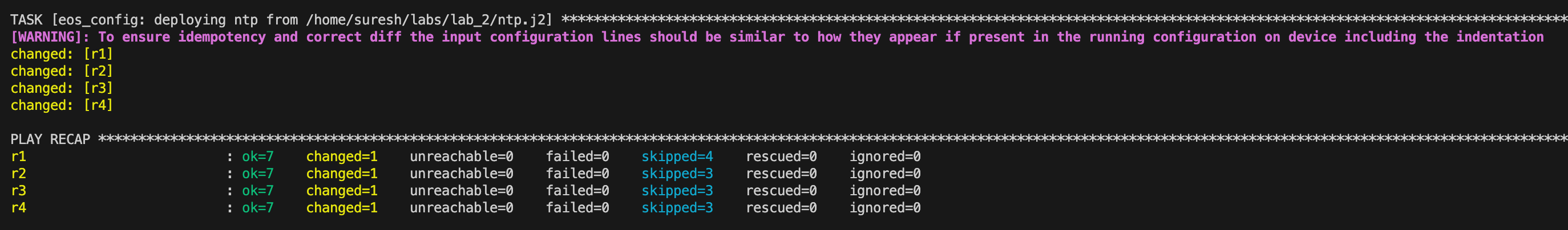
Now, if you log in to the devices, you can see the custom configuration applied.
netlab connect r2
Connecting to clab-lab2-r2 using SSH port 22
Last login: Sat Aug 23 18:41:30 2025 from 192.168.200.1
r2#
r2#
r2#
r2#show run | incl ntp
ntp server 1.1.1.1
So, we now know how to push configs to an already running lab using the netlab config command, but ideally we want to include this as part of our lab build so we don’t have to do it later. To achieve this, we can use the groups section in the topology file. By adding config: [ ntp ] under the all group, Netlab will automatically apply the ntp.j2 template to every device during the initial deployment.
provider: clab
defaults.device: eos
defaults.devices.eos.clab.image: ceos:4.34.2

addressing:
  mgmt:
    ipv4: 192.168.200.0/24
  p2p:
    ipv4: 172.16.1.0/24
    prefix: 30

groups:
  all:
    config: [ ntp ]

module: [ ospf ]
nodes: [r1, r2, r3, r4]
links:
  - r1-r2
  - r2-r3
  - r3-r4
In this example, the all group covers all nodes in the lab, and the custom configuration is applied when we run netlab up. You still need to keep the ntp.j2 file in the root of your project (same directory as the topology file), but now you can just run netlab up and the custom configuration will be deployed automatically.

Switching to Cisco
Now, let’s say I want to deploy the same lab using Cisco devices. Going back to my initial point, if you were using EVE-NG, GNS3, or CML, you would need to create a new lab, add Cisco nodes, set up the links, and configure everything again. With Netlab (and the same applies if you use containerlab standalone), all we need to do is update two lines in the topology file to point to the Cisco image. Everything else stays the same.
provider: clab
defaults.device: iol
defaults.devices.iol.clab.image: iol:17.12.01

addressing:
  mgmt:
    ipv4: 192.168.200.0/24
  p2p:
    ipv4: 172.16.1.0/24
    prefix: 30

groups:
  all:
    config: [ ntp ]

module: [ ospf ]
nodes: [r1, r2, r3, r4]
links:
  - r1-r2
  - r2-r3
  - r3-r4
I’ve already covered how to add Cisco IOL images to containerlab in a previous post, so feel free to check that out.
Once the image reference is updated, we can simply run netlab up and the exact same lab is now running with Cisco devices.
netlab connect r2
Connecting to clab-lab4cisco-r2 using SSH port 22
r2#
r2#show ip ospf neighbor

Neighbor ID     Pri   State           Dead Time   Address         Interface
10.0.0.3          0   FULL/  -        00:00:38    172.16.1.6      Ethernet0/2
10.0.0.1          0   FULL/  -        00:00:38    172.16.1.1      Ethernet0/1
r2#
r2#
r2#show ver | incl Cisco
Cisco IOS Software [Dublin], Linux Software
(X86_64BI_LINUX-ADVENTERPRISEK9-M), Version 17.12.1,
RELEASE SOFTWARE (fc5)
Copyright (c) 1986-2023 by Cisco Systems, Inc.
MPLS Lab
Let’s look at another example where we deploy an MPLS lab with five routers using Cisco. In this lab, I also want to allocate MPLS label ranges for each device. For instance, r1 will use labels 100–199, r2 will use 200–299, r3 will use 300–399, and so on.
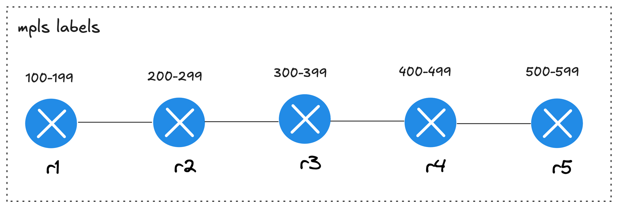
Unlike our earlier example, where the same custom configuration was applied to all devices, here each device gets its own configuration. To achieve this setup in Netlab, we can create a directory (called labels) that holds individual configuration templates, where each file name matches the node name.
.
├── labels
│   ├── r1.j2
│   ├── r2.j2
│   ├── r3.j2
│   ├── r4.j2
│   └── r5.j2
└── topology.yml
For r1, the configuration looks like this. After assigning the label ranges, I’m disabling MPLS and then re-enabling it so that the routers use the new labels.
mpls label range 100 199
no mpls ip
mpls ip
And, this is the topology file (topology.yml) for the MPLS lab. Here, I’m also specifying the loopback IP of each device using the loopback key. This makes it easier to identify and reach each router in the MPLS topology. With OSPF and MPLS enabled as modules, plus the loopback addresses defined, the lab comes up fully configured and ready for testing.
provider: clab
defaults.device: iol
defaults.devices.iol.clab.image: iol:17.12.01

addressing:
  mgmt:
    ipv4: 192.168.200.0/24
  p2p:
    ipv4: 172.16.1.0/24
    prefix: 30

module: [ ospf, mpls ]

groups:
  all:
    config: [ labels ]

nodes:
  - name: r1
    loopback:
      ipv4: 1.1.1.1/32
  - name: r2
    loopback:
      ipv4: 2.2.2.2/32
  - name: r3
    loopback:
      ipv4: 3.3.3.3/32
  - name: r4
    loopback:
      ipv4: 4.4.4.4/32
  - name: r5
    loopback:
      ipv4: 5.5.5.5/32

links:
  - r1-r2
  - r2-r3
  - r3-r4
  - r4-r5
After deploying the lab, I can log in to r2 for example, and check the MPLS forwarding table.
r2#show mpls forwarding-table
Local      Outgoing   Prefix           Bytes Label   Outgoing   Next Hop
Label      Label      or Tunnel Id     Switched      interface
200        Pop Label  1.1.1.1/32       0             Et0/1      172.16.1.1
201        Pop Label  3.3.3.3/32       0             Et0/2      172.16.1.6
202        302        4.4.4.4/32       0             Et0/2      172.16.1.6
203        303        5.5.5.5/32       0             Et0/2      172.16.1.6
204        Pop Label  172.16.1.8/30    0             Et0/2      172.16.1.6
205        305        172.16.1.12/30   0             Et0/2      172.16.1.6
You can also have multiple custom configs. We can still keep ntp.j2 in the lab root so it applies to every device, and keep the per-node label templates inside the labels directory. With this setup, netlab up will push the device-specific label ranges and the common NTP config in one go.
groups:
  all:
    config: [ labels, ntp ]
We can also apply specific configs to a subset of devices instead of all of them. For example, let’s say I want to push an additional NTP server only to r1 and r2. We can create another template called ntp_dc.j2 in the root of the project with the line ntp server 192.168.10.10. Then I update the topology file to include a new group only for r1 and r2.
ntp server 192.168.10.10groups:
ntp_dc:
members: [ r1, r2 ]
config: [ ntp_dc ]
all:
config: [ labels, ntp ]With this, when the lab is deployed, r1 and r2 will have two NTP servers configured, while r3, r4, and r5 will only have the common one defined in ntp.j2.
r1#show run | incl range
mpls label range 100 199
r1#
r1#show run | incl ntp
ntp server 192.168.10.10
ntp server 10.10.10.10
r2#show run | incl range
mpls label range 200 299
r2#
r2#show run | incl ntp
ntp server 192.168.10.10
ntp server 10.10.10.10r3#show run | incl range
mpls label range 300 399
r3#
r3#show run | incl ntp
ntp server 10.10.10.10BGP Lab
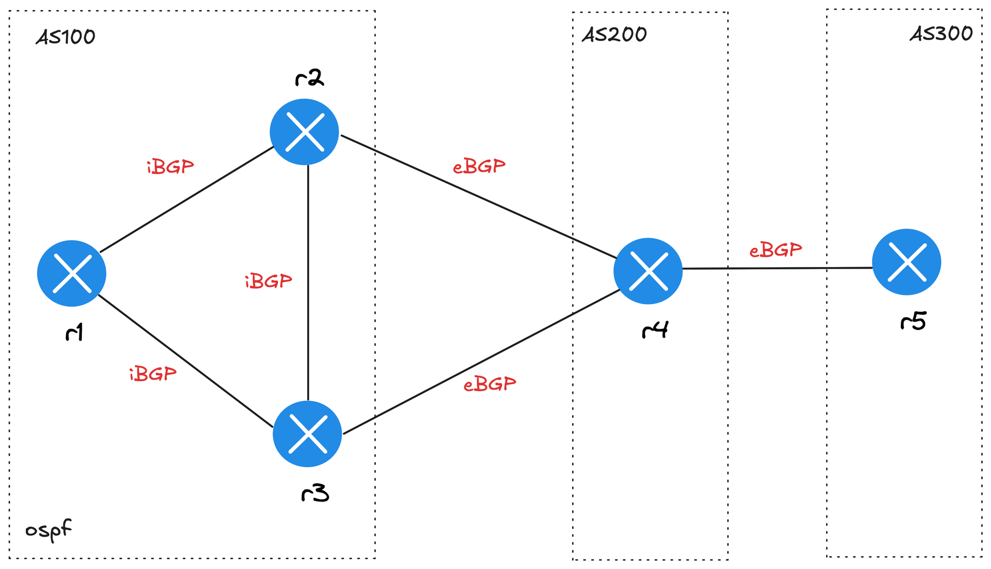
Let’s look at a BGP lab before wrapping up. The goal here is to build a working BGP lab so we can focus on testing BGP path attributes, for example. The diagram shows three routers (r1, r2, r3) in AS100 running OSPF and iBGP between them. Router r4 is in AS200, and router r5 is in AS300.
provider: clab
defaults.device: iol
defaults.devices.iol.clab.image: iol:17.12.01

addressing:
  mgmt:
    ipv4: 192.168.200.0/24
  p2p:
    ipv4: 172.16.1.0/24
    prefix: 30

nodes:
  - name: r1
    module: [ ospf, bgp ]
  - name: r2
    module: [ ospf, bgp ]
  - name: r3
    module: [ ospf, bgp ]
  - name: r4
    module: [ bgp ]
  - name: r5
    module: [ bgp ]

bgp:
  advertise_loopback: false
  as_list:
    100:
      members: [ r1, r2, r3 ]
    200:
      members: [ r4 ]
    300:
      members: [ r5 ]

links:
  - r1
  - r1-r2
  - r1-r3
  - r2-r3
  - r2-r4
  - r3-r4
  - r4-r5
One thing to note is that under the links section, we have r1 without a connection, which creates a stub link. I also set advertise_loopback: false so loopback addresses are not advertised by BGP. The stub network on r1 (172.16.0.0/24 in this case) is the prefix that gets advertised. Here are the configs that got generated on r1.
r1#show run | sec bgp
router bgp 100
 bgp router-id 10.0.0.1
 bgp log-neighbor-changes
 bgp nopeerup-delay cold-boot 1
 bgp nopeerup-delay user-initiated 1
 bgp update-delay 5
 no bgp default ipv4-unicast
 neighbor 10.0.0.2 remote-as 100
 neighbor 10.0.0.2 description r2
 neighbor 10.0.0.2 update-source Loopback0
 neighbor 10.0.0.3 remote-as 100
 neighbor 10.0.0.3 description r3
 neighbor 10.0.0.3 update-source Loopback0
 !
 address-family ipv4
  bgp scan-time 5
  network 172.16.0.0 mask 255.255.255.0
  neighbor 10.0.0.2 activate
  neighbor 10.0.0.2 send-community both
  neighbor 10.0.0.2 next-hop-self
  neighbor 10.0.0.3 activate
  neighbor 10.0.0.3 send-community both
  neighbor 10.0.0.3 next-hop-self
 exit-address-family
ip bgp-community new-format
Once the lab is up, if we log in to r5, we can verify that it receives the prefix originating from r1’s stub network. This gives us a minimal but complete BGP lab where we can start testing and exploring BGP path attributes or any other bits and pieces.
r5#show ip bgp summary | beg Neighbor
Neighbor        V           AS MsgRcvd MsgSent   TblVer  InQ OutQ Up/Down  State/PfxRcd
172.16.1.21     4          200      17      16        2    0    0 00:11:06        1
r5#show ip bgp neighbors 172.16.1.21 routes | beg Network
Network Next Hop Metric LocPrf Weight Path
*> 172.16.0.0/24 172.16.1.21 0 200 100 i
Total number of prefixes 1If you look at the configs generated on r1, you may notice that it has next-hop self enabled. This is the default behaviour of the Netlab BGP module. If you don’t want this, you can easily disable it by setting next_hop_self: false. This is a good example of how flexible Netlab is and how quickly you can adjust the lab to match what you want to test.
bgp:
  advertise_loopback: false
  next_hop_self: false
r1#show run | sec bgp
router bgp 100
bgp router-id 10.0.0.1
bgp log-neighbor-changes
bgp nopeerup-delay cold-boot 1
bgp nopeerup-delay user-initiated 1
bgp update-delay 5
no bgp default ipv4-unicast
neighbor 10.0.0.2 remote-as 100
neighbor 10.0.0.2 description r2
neighbor 10.0.0.2 update-source Loopback0
neighbor 10.0.0.3 remote-as 100
neighbor 10.0.0.3 description r3
neighbor 10.0.0.3 update-source Loopback0
!
address-family ipv4
bgp scan-time 5
network 172.16.0.0 mask 255.255.255.0
neighbor 10.0.0.2 activate
neighbor 10.0.0.2 send-community both
neighbor 10.0.0.3 activate
neighbor 10.0.0.3 send-community both
exit-address-family
ip bgp-community new-format
r1#
Multi Vendor Lab
You can also mix multiple vendors in the same lab. Using our previous BGP example, we can run Arista on r5 and Juniper on r4. Nothing else changes; we just need to tell Netlab which images to use and specify the vendor for those nodes. This makes it really easy to test interoperability between different platforms without having to redesign the lab.
provider: clab
defaults.device: iol
defaults.devices.iol.clab.image: iol:17.12.01
defaults.devices.eos.clab.image: ceos:4.34.2
defaults.devices.vmx.clab.image: vmx:24.2R1-S2.5

addressing:
  mgmt:
    ipv4: 192.168.200.0/24
  p2p:
    ipv4: 172.16.1.0/24
    prefix: 30

nodes:
  - name: r1
    module: [ ospf, bgp ]
  - name: r2
    module: [ ospf, bgp ]
  - name: r3
    module: [ ospf, bgp ]
  - name: r4
    device: vmx
    module: [ bgp ]
  - name: r5
    device: eos
    module: [ bgp ]

bgp:
  advertise_loopback: false
  next_hop_self: false
  as_list:
    100:
      members: [ r1, r2, r3 ]
    200:
      members: [ r4 ]
    300:
      members: [ r5 ]

links:
  - r1
  - r1-r2
  - r1-r3
  - r2-r3
  - r2-r4
  - r3-r4
  - r4-r5
Output from r4 (Juniper vMX)
netlab connect r4
Connecting to clab-multivendorb-r4 using SSH port 22
Last login: Sun Aug 24 11:31:32 2025 from 192.168.100.1
--- JUNOS 24.2R1-S2.5 Kernel 64-bit  JNPR-15.0-20241031.1c96ec0_buil
admin@r4> show version
Hostname: r4
Model: vmx
Junos: 24.2R1-S2.5
admin@r4> show route advertising-protocol bgp 172.16.1.22
inet.0: 8 destinations, 9 routes (8 active, 0 holddown, 0 hidden)
Prefix Nexthop MED Lclpref AS path
* 10.0.0.4/32 Self I
* 172.16.0.0/24 Self 100 I
* 172.16.1.12/30 Self I
* 172.16.1.16/30 Self I
* 172.16.1.20/30 Self IOutput from r5 (Arista EOS)
r5#show ver
Arista cEOSLab
Hardware version:
Serial number: 734E2F7AD7E9485DC883A2A476A1EDFE
Hardware MAC address: 001c.7374.096e
System MAC address: 001c.7374.096e

Software image version: 4.32.2.1F-38881786.43221F (engineering build)
r5#show ip bgp neighbors 172.16.1.21 received-routes | beg Network
Network Next Hop Metric AIGP LocPref Weight Path
* > 10.0.0.4/32 172.16.1.21 - - - - 200 i
* > 172.16.0.0/24 172.16.1.21 - - - - 200 100 i
* > 172.16.1.12/30 172.16.1.21 - - - - 200 i
* > 172.16.1.16/30 172.16.1.21 - - - - 200 i
* > 172.16.1.20/30 172.16.1.21 - - - - 200 i
Netlab Collect
If you remember, I mentioned that when you run netlab down and then netlab up, all your device configs are wiped out. But there are times when you make local changes and don’t want to lose them. For example, I added an NTP server to r5 in the previous BGP lab and saved the config. If I were to run netlab down, those changes would be gone.
r5(config)#ntp server 1.1.1.1
r5(config)#end
r5#wr
Building configuration...
[OK]
This is where netlab collect command can help. It uses Ansible device facts (or equivalent modules) to collect device configurations and save them in a specified directory. By default, the configs are stored under the folder config. Once collected, you can safely run netlab down and later restart the lab with the saved configs using netlab up --reload-config config.
config
├── r1.cfg
├── r2.cfg
├── r3.cfg
├── r4.cfg
└── r5.cfg

0 directories, 5 files--cleanup flag, so be careful if you want to preserve your changes.A Few Things to Remember and Closing Up
One thing I want to point out is that by default, you can’t run multiple labs at the same time on the same server. There is a multilab plugin that allows you to do this, and the official documentation covers it in detail if you’re interested. I haven’t tried it myself yet, but if I do, I’ll make sure to update this post.
To wrap up, I hope this gave you a good idea of what Netlab can do and how it can make building and sharing labs easier. Again, just because I find it useful doesn’t mean it will fit every use case. Always go with whatever tool works best for you and your workflow. Huge thanks to Ivan Pepelnjak for putting this tool together.